on-off delay timer connection with contactor
Learn how to wire a control on a delay timer with a contactor. Step-by-step input-to-output wiring, testing, and safety tips for automation.

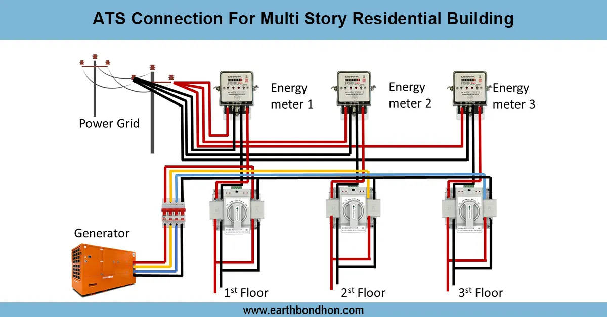
on delay timer contactor wiring
Connect the supply to the on delay timer, the output of which is connected to the coil of the contactor (A1 -A2).Following the preset delay, the load is switched ON by activating the coil and the load.
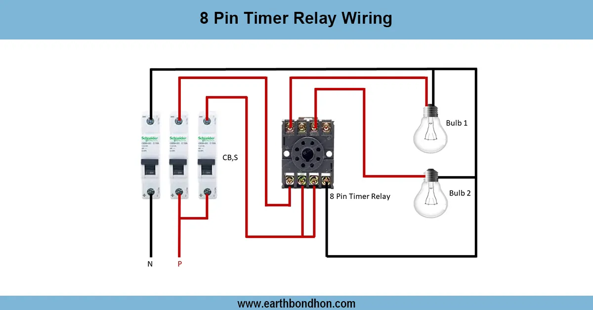
motor on delay contactor wiring
A delay timer control in contactor wiring is a handy automation configuration to delay a load switch-on after coming on.
The timer on the delay switches on only after a predetermined delay, and this delay is then utilized to switch the contactor coil (A1–A2). This is used to guarantee that the load connected, motors, pumps, fans, or HVAC system do not start with a sudden inrush current or unwanted starting.
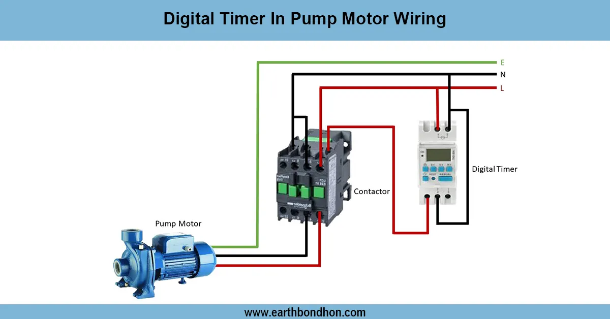
The timer is fed in this type of wiring. When it is fed with an input signal, the timer counts its delay preset. Once this time has passed, it activates the output relay in order to provide power to the contactor coil. The contactor then closes its main contacts, and the power is connected to the load.
This is needed in the automation of industries, including motor protection, pump sequencing, and generators with staggered or delayed starts to avoid overloading the system. Safety and reliability can be obtained through proper usage of MCB/RCCB, earth connections, and control fuses.
Work / Installation (Inputs → Outputs)
Input: Supply → MCB/RCCB → On Delay Timer.
- Feed phase and neutral to the timer’s input.
- Set the required delay time on the timer (seconds/minutes).
- Connect the timer’s relay output to A1 of the contactor coil, and connect A2 to neutral.
- Pass the main phase through the contactor’s input (L1, L2, L3) and take the output from T1, T2, T3. For single-phase, use one pole.
- Connect neutral directly to the load (or via 2-pole contactor if needed).
- Bond earth properly to load and metal parts.
Output: When power is supplied, the timer waits for the preset time, then energizes the contactor coil, which connects the load.
Testing & Final Adjustments
Install and set the on delay timer to use a short test delay (e.g., 5 seconds). Turn ON the supply and monitor: the timer must await the programmed time before activating the contactor coil. Check the voltage at A1- A2 at ON. Ensure that the load does not begin before the delay.
Check the operation of the MCB/RCCB and the proper phase/neutral connections polarity. Measure load current to ensure that there is no direct inrush at start. Set the timer delay to the required value to suit your application (longer delay required with sequential pumps).
Install ferrules, screw on terminals, and stitch wiring. Apply a small fuse in the control circuit and surge protection to the coil to protect to system's life. After testing, label the wiring to make it easy to troubleshoot.
This guarantees the safe, efficient, and reliable delayed start control in pumps, motors, lighting, or HVAC systems.