Timer light switch wiring Diagram
Learn manual auto switch installation wiring diagram with input-output setup, safe connections, and testing for smooth operation of electrical devices.

manual auto switch installation wiring diagram
WA wire to connect a manual auto switch with the supply connected to the input and the outputs to manual and automatic circuits, allowing flexible operation of devices.
input output wiring of manual auto switch
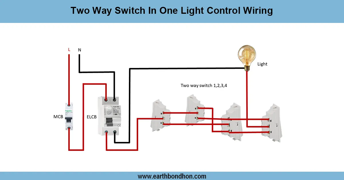
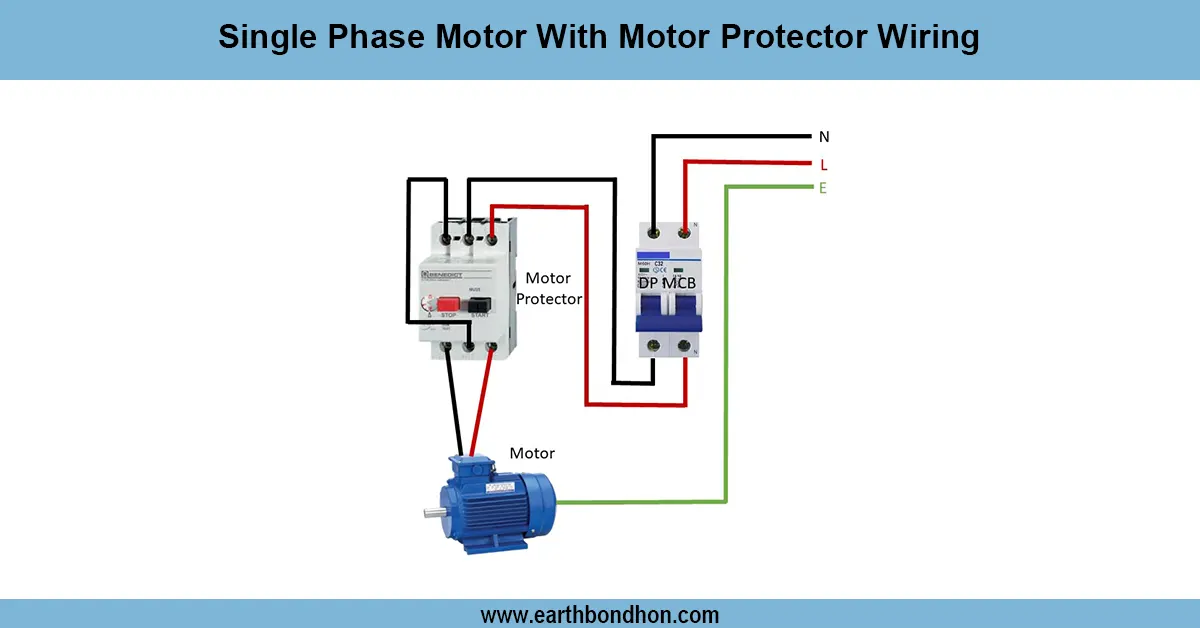
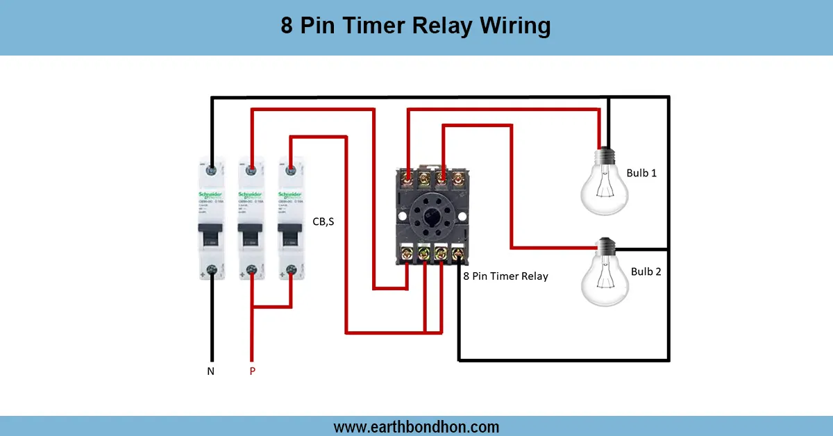
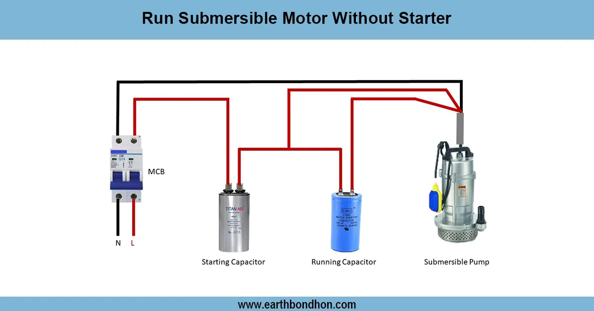
A manual auto switch installation wiring diagram details the wiring to connect an installation switch that provides you with the ability to turn equipment on or off manually or automatically. This kind of switch has been utilized on water pumps, motors, generators, and control panels. The wiring is the connection of the main supply to the common input terminal of the switch. The output of one of the devices is connected to the manual circuit, in which the device is directly operated, and the other output is connected to the automatic control system, like a timer, sensor, or relay. When the switch is turned on, it allows users to choose to use manual control or automatic operation. When the appliances are properly wired, this will guarantee safe operation, preventing overloading and abuse of the appliances.
Work / Installation (Inputs → Outputs)
Before installation, Turn OFF the main power. Install the manual auto switch in an enclosed and secure area, ideally a control box. Connect the phase and neutral wires of the main supply to the two input terminals of the switch. On the output side, one terminal is connected to the manual line (direct device control) and the other is connected to the automatic control line (timer, float switch, or sensor). Provide earthing, if it is given, connect it appropriately. Ensure that all the connections are tight, insulated, and labelled. Proper wire size depending on the load of the device. Once wired, close the panel and make sure the switch travels freely between the manual and the auto.
Testing & Final Adjustments
Turn ON the main supply after wiring is done. First, you need to test the manual mode: the device must work when directly turned ON. Then turn the switch to auto mode and ensure that the attached automatic controller (timer, sensor, or relay) operates the device as desired. Measure the correct input and output voltage with a multimeter. Be sure there is no sparking or heating of connections. Should the device fail in either mode, check wiring connections. Change the settings of the automatic system as needed. Lastly, provide a manual and auto-marked switch to enable ease of operation and sensitize the users on proper switching to avoid electrical faults. Check connections regularly to provide safety and reliability.