Two way switch fan regulator connection
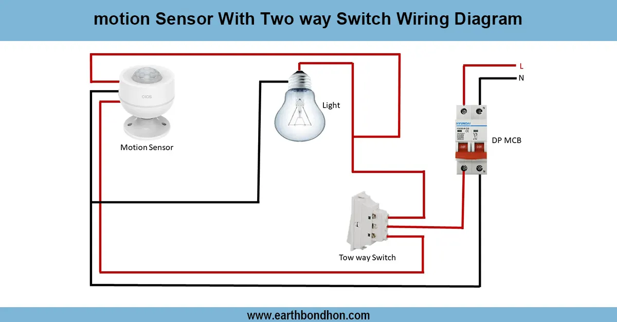
Wiring diagram for controlling two separate light regulators from two locations using two-way switches for flexible ON/OFF control.

two way switch two regulator wiring
A two-way switch three regulator means that two of the regulators can be controlled independently in two different locations with pairs of SPDT switches and traveler wiring on each circuit.
Formula & Table Summary:
Components: Four SPDT switches (two pairs), two light regulators, live (L), neutral (N), traveler wires.
Connections: Each pair of two way switches connects via traveler wires; switch commons connect to live supply and respective regulator inputs; regulators connect to neutral.
Operation: Each regulator controlled independently by toggling either switch in its pair.
Safety: Turn off power before installation and use appropriate wire gauges and protections.
| Component | Connection | Function |
|---|---|---|
| Switch Pair 1 Common | Connect to Live supply | Power input for Regulator 1 |
| Switch Pair 1 Travelers | Connect between Switch 1 and 2 | Switching paths for Regulator 1 |
| Regulator 1 Input | Connect to Switch Pair 1 Common terminal | Control input |
| Switch Pair 2 Common | Connect to Live supply | Power input for Regulator 2 |
| Switch Pair 2 Travelers | Connect between Switch 3 and 4 | Switching paths for Regulator 2 |
| Regulator 2 Input | Connect to Switch Pair 2 Common terminal | Control input |
| Neutral | Connects to Regulators | Completes circuit |
electrical wiring two regulators
This wiring is to activate two independent light regulator found on two different switch location through two way switches. The different regulators operate individual lights/fans allowing them to be switched ON/OFF independently at two locations. The wiring includes two sets of two-pole-two-throw (SPDT) switches,one set with each regulator,wired with traveler cables between the two switch locations. The individual regulator is connected to individual switch common terminal and neutral. The arrangement is convenient when it is used in rooms, which have several entries or with the aim of regulating various light segments conveniently.
two way switch installation
| Regulator 1 Switch Positions | Regulator 2 Switch Positions | Regulator 1 Status | Regulator 2 Status |
|---|---|---|---|
| Up - Up | Up - Up | OFF | OFF |
| Up - Down | Down - Up | ON | ON |
| Down - Up | Up - Down | ON | ON |
| Down - Down | Down - Down | OFF | OFF |