
Switch board wiring connection
Learn how to wire a switchboard with fan, light, and socket connections. Clear diagram and safe installation guide for home electrical wiring.

home switch board connection
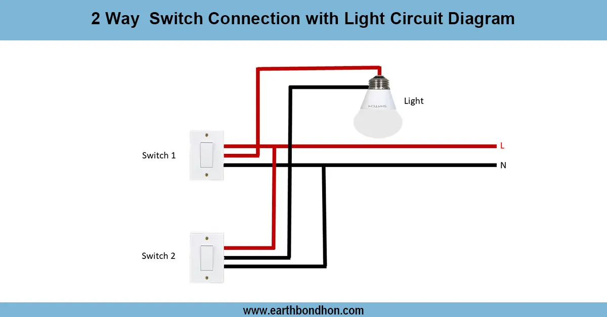
A switchboard wiring schematic is a wiring diagram connecting the incoming phase (Line) to individual switch, which then feeds loads (lights, fans, and sockets) to loads. Neutral leads directly to the appliances, and the board and sockets are bonded to Earth. Speed control is provided by connecting the fan regulator in series with the phase wire of the fan.
single phase switch board wiring
A switchboard wiring diagram demonstrates the connections between lights, fans, and sockets to make a single panel safe to use at home. In domestic wiring, the phase (Line/Live) is taken to every switch terminal, and the neutral is taken directly to the load, e.g., lights, fans, or sockets. The phase of the socket is fed through a switch, and then the neutral is passed to the socket. The fan is wired to a fan regulator in series with the phase of the fan. All metallic components of the board and socket connections are connected to earthing. Proper choice of wire color (phase red/brown, neutral black/blue, and earth green) needs to be taken. Such a configuration allows convenient management of several appliances using a single switchboard.
Work, Installation — Inputs → Outputs
Inputs: Line (phase), Neutral, Earth, switches, sockets, fan regulator, loads (fan/light).
Process:
- Switch off mains power.
- Mount switch board frame.
- Connect Line input to all switch terminals (looping).
- Run output wires from switches to respective loads.
- Connect Neutral wires directly from supply to each load/socket.
- Wire regulator in series with fan phase.
- Connect Earth to board, socket, and appliance body.Outputs: Light and fan turn ON/OFF by switches; socket supplies power; fan regulator adjusts speed.
Testing and Final Adjustments
Once the switchboard has been wired, reconnect the power and verify the individual switches one at a time. Turn the light switch on and off to verify the bulb is glowing, turn on the fan switch and regulator to verify speed changes, and use a tester or small load to test the socket. Make sure that the earthing connection is correct with a test lamp or multimeter. Where a switch does not work, check the phase connection or output connection. #4 Loose terminals can be a source of sparks or heating; therefore, screws should be tightened accordingly. Label all switches (e.g., Light, Fan, Socket). You should never forget to ensure that switches and sockets are of the appropriate load capacity to avoid excessive overheating.
Frequently Asked Questions - Switch board wiring connection:
What is a switch board wiring diagram?
It shows how switches, sockets, and regulators are wired together to control appliances.
Which wire goes to the switch?
Only the phase (live) wire is connected to switch terminals; neutral goes directly to loads.
How is a fan regulator connected?
It is connected in series with the fan’s phase wire to adjust speed.
Do sockets need switches?
Yes, for safety the phase wire of a socket passes through a switch before reaching the socket.
What is the role of the earth wire?
The earth wire connects to metallic parts and sockets for protection from shocks.
Can one switch board control multiple loads?
Yes, a single switch board can control lights, fans, and sockets by looping phase to each switch.
What wire colors are used?
Phase is red/brown, neutral is black/blue, and earth is green/yellow.
What if the fan does not work?
Check regulator wiring and ensure the phase is properly connected through the switch and regulator.
Is neutral ever connected to switches?
No, only the phase wire is switched; neutral goes directly to the load.
Is it safe to do wiring myself?
Yes, if you follow safety precautions and shut off power; otherwise hire an electrician.