Timer Switch Connection Diagram
Learn how to wire a timer switch to control AC, lights, or appliances automatically, including proper input, output, and protective wiring.

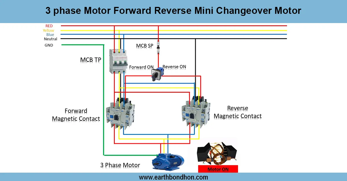
timer switch wiring diagram for ac connection
The wiring diagram of the timer switch connection demonstrates the assembly of supplying and loading the appliances or lights in a way that appliances or lights will automatically switch ON and OFF at predetermined times, thus enhancing convenience and saving power.
timer switch connection for lighting load:
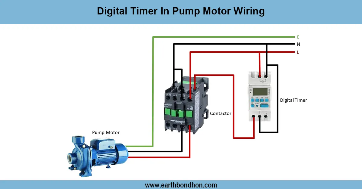
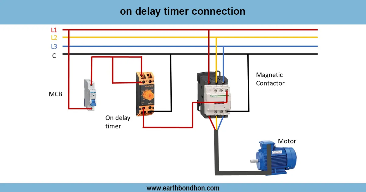
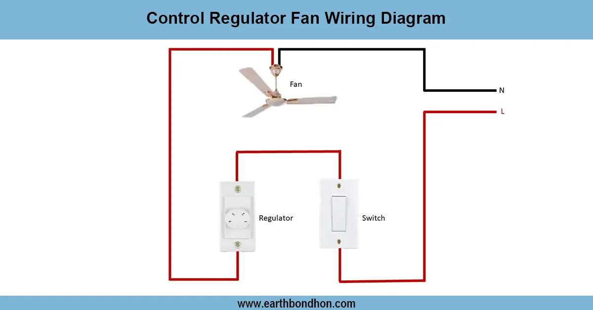
A timer switch is used to automatically turn on and off electrical appliances, lights, or AC loads based on a predetermined program. Wiring requires that the supply, composed of live (L) and neutral (N) supply, be connected to the timer input terminals, and the load be connected to the timer output terminals. The live wire should have the protective measures installed in series with protective equipment (MCB or fuse) to eliminate chances of overloading or short circuit. The timing and appliances that are connected should be earthed properly to make them safe. Timer switches may either be mechanical or electronic, with a variable programming of daily or weekly schedules. It is a common installation of this type of wiring in both residential and commercial, and industrial settings to conserve power, automate processes, and work more efficiently. Using the wiring diagram makes sure it works properly, minimizes human input, and safeguards equipment that is connected.
Work & Installation (Input → Output,)
- AC Supply Input: Connect live (L) and neutral (N) to the timer input terminals.
- Load Connection: Connect the electrical load (light, fan, AC, or other appliances) to the timer output terminals.
- Protection Devices: Install an MCB or fuse in series with the live wire to protect the circuit from overload or short circuit.
- Earthing: Properly earth the timer switch and any connected metallic appliances.
- Timer Setting: Adjust the ON and OFF times according to operational requirements.
- Operation: At the preset ON time, the timer energizes the load; at the OFF time, it disconnects power automatically.
- Output: The load operates automatically according to schedule, conserving electricity and reducing manual operation.
Testing & Final Adjustments
Wire and check timer display. Once wired, switch ON the main supply. Test the immediate ON/ OFF operation by use of the manual override (where applicable). Note the attached load to check how it works properly at the scheduled time. Check all wiring by making sure they are securely connected, well insulated, and correctly earthing. Ensure that the protective devices (MCB/fuse) are of the right rating for the load. Set the clock to the right ON/OFF time. Identify the wiring to be easily identified. Periodic check-ups can ensure that timers work well, as well as increase the life of the appliances linked to them. Proper installation leads to the elimination of electrical risk, overloading, and energy efficiency.