Electrical Relay Wiring
Learn pulse relay connection wiring with switch control. Step-by-step guide to connect input, output, and load for safe electrical installation.

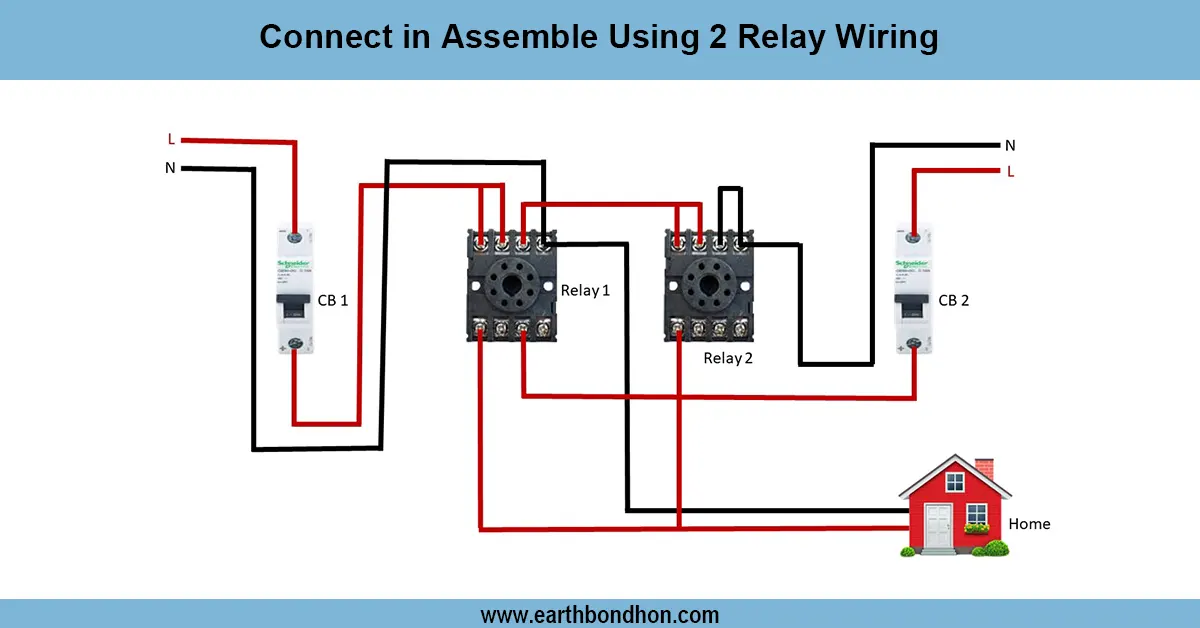
pulse relay connection wiring diagram
A pulse relay wiring diagram is a diagram demonstrating how a relay closes/recloses with a pulse of a push button to control multiple points or loads of light or power.
push button relay connection diagram
A pulse relay connection wiring diagram is a circuit diagram describing how to wire a relay to use a short pulse signal, rather than continuous current. A pulse relay (step relay), in contrast to a normal relay, switches its state (ON/OFF) every time it is addressed by a control pulse, when a push button or switch is released. The benefit of this is that you can operate one load at numerous points using tiny momentary switches, so the wiring is less complex. The wiring is not complicated. Connect the power supply (L and N) to the relay input, the load (light, fan, or motor) to the relay output, and the push button in parallel to the pulse input terminal. The relay turns the load ON or OFF when a pulse is sent by any switch. Pulse relays find numerous applications in lighting systems, smart houses, and automation circuits, thus making energy control more effective.
Work / Installation (Inputs → Outputs)
- Switch OFF the main supply before wiring.
- Connect Phase (L) and Neutral (N) from supply to the input terminals of the pulse relay.
- Connect the load (light/fan) to the relay output terminals.
- Connect push button switches in parallel to the relay’s pulse control input.
- Earthing must be connected to the load if required.
👉 When a button is pressed, the relay coil gets a pulse and toggles its contacts.
👉 If the load was OFF, it turns ON; if it was ON, it turns OFF.
This setup allows multiple push buttons to control the same load without needing 2-way or intermediate switch wiring.
Testing & Final Adjustments
Once wired, use the power again. Test with any push button: the load must switch ON and OFF. Press once more to check the astable switch. Where the relay is not responding, ensure the coil connections are in place and the control pulse switches are wired in parallel. Note, also, that the voltage rating of the relay should be the same as the supply (e.g., 230 V AC or 12 V DC). Check all push buttons to make sure that multi-point control functions. To be on the safe side, connect up everything with insulation, and put the relay in a strong box. Have the relay periodically inspected to determine whether it is overheated or has loose terminals. Pulse relays are energy-efficient and long-lasting because they operate on short pulses rather than on constant power. This guarantees good automation of home and industrial circuits.