

Switch Electrical Wiring diagram
Learn electrical switch board wiring with step-by-step guide, installation process, safety tips, and testing for proper function.

electrical switch board wiring diagram
Electrical switchboard wiring is the connection of input power supply lines (phase, neutral, and earth) to the board and then supplying them to output loads via switches and sockets. It maintains the safety of using fans, lights, and appliances, and prevents any faults in the system.
switch board connection wiring
Wiring of electrical switchboards is a necessity in home and office electrical systems. It provides a safe transfer of power to fans, lights, and appliances. A switchboard is a board that connects the incoming power supply to various circuits with switches, sockets, regulators, and indicators. Installation of proper wiring involves knowledge of live, neutral, and earth connections, as well as proper use of protective equipment like MCBs. Adequate connections, the correct sizing of wires, and precautions should be taken to avoid possible dangers like short circuiting, overloading, or electric shocks. When the switchboard is well installed, tested, and adjusted, it serves effectively to give a reliable power supply.
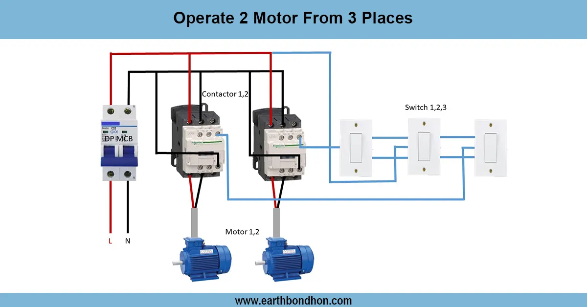
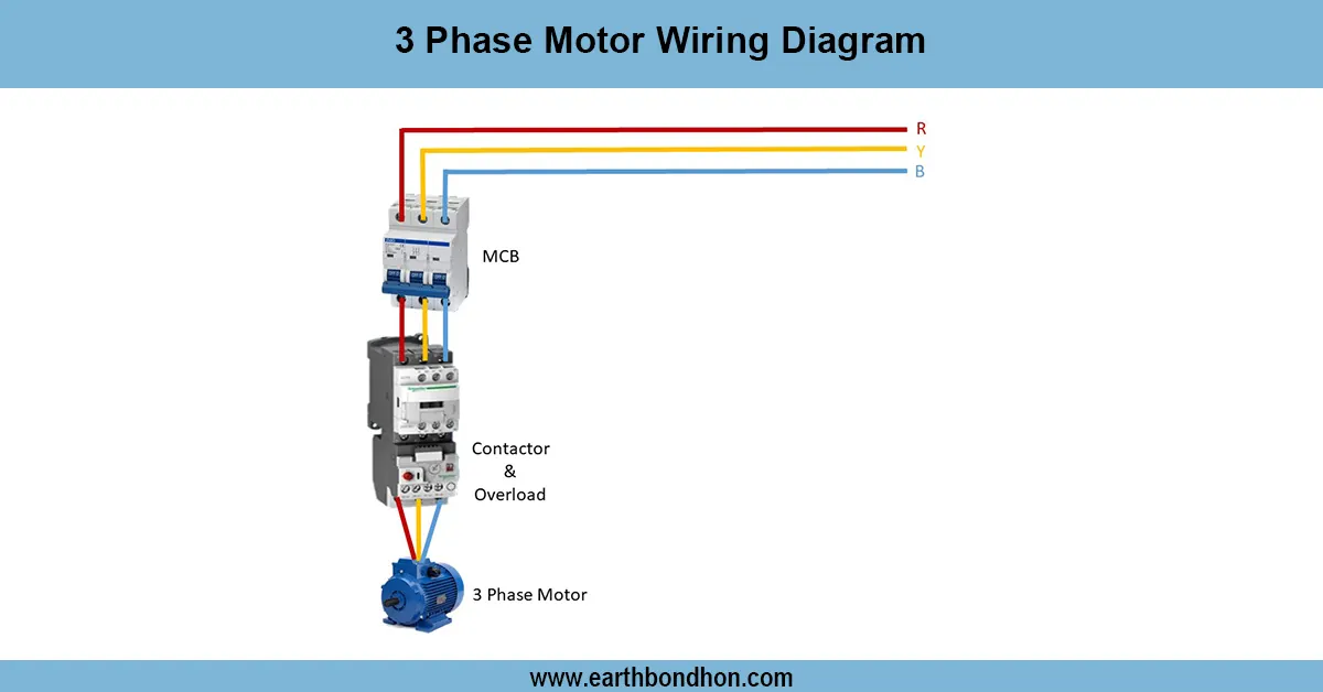
Work / Installation (Inputs → Outputs)
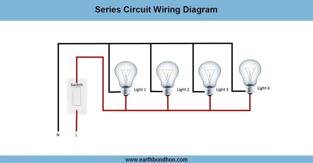
A wire board of electrical switches is wired, and the power supply, which comes in through the main distribution line, is connected. The phase wire and neutral wire are connected respectively to the individual switches and directly to the output appliances and the earthing terminal. Each switch is a kind of controller that opens and closes the flow of electricity to a load (a light, fan, socket, etc.). The board also includes regulators of fans and sockets of appliances. In order to make sure that they are properly installed, the wires must be well-insulated, hooked up with firm terminals, and also organized so that they do not short out. Proper distribution of loads, installation of MCB, and compliance with electrical codes are required.
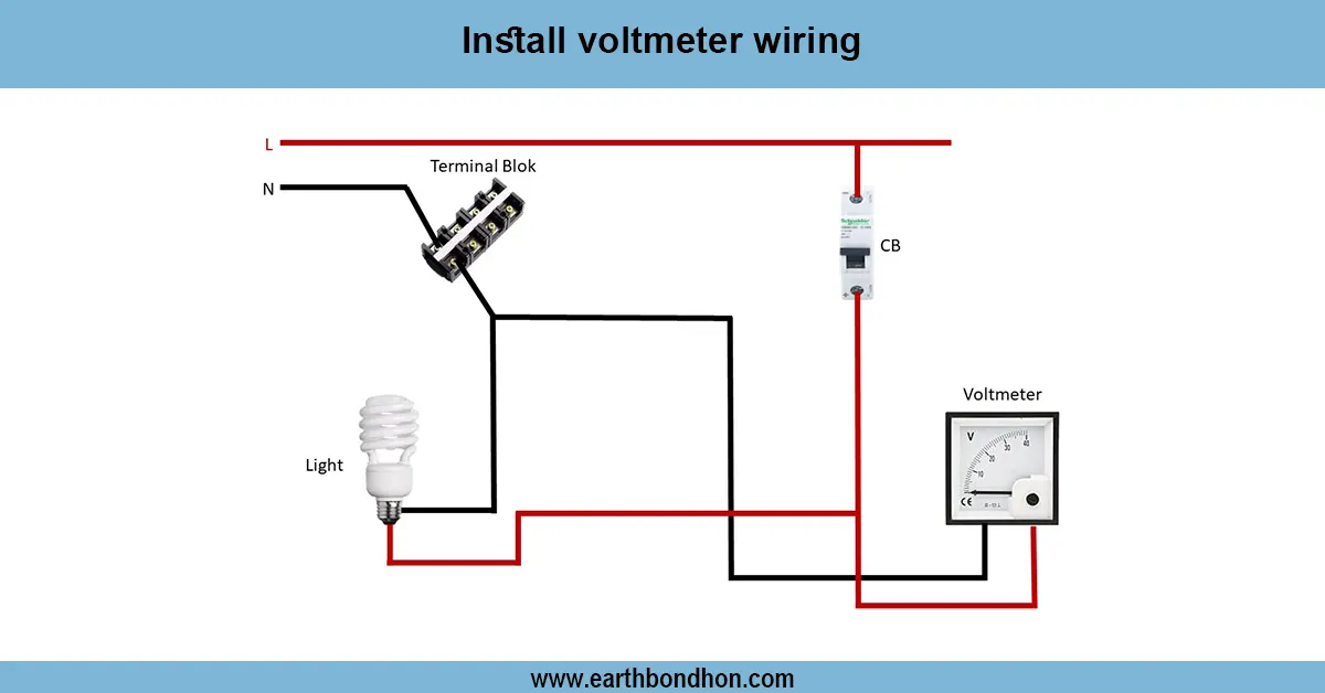
Testing & Final Adjustments
Once switchboard wiring is done, it is necessary to conduct tests to make sure that the switchboard works safely and reliably. First, ensure that all connections are tight and that live, neutral, and earth wires are in place. Test to identify the phase and verify that there is a connection to Earth. Turn on the power supply and shift the switches, sockets, and regulators to ensure they are working. Test all suspicious sparking, overheating, or loose fittings. In case of a problem, switch off the supply and check the wiring again. After confirmation, arrange the wiring well, tighten the switchboard cover, and cover the switches so that they can be identified easily. Final modifications provide long-life performance and electrical safety.
Frequently Asked Questions - Switch Electrical Wiring diagram:
What is electrical switch board wiring?
It is the process of connecting switches, sockets, and regulators to distribute electricity from input to output loads.
Which wires are used in switch board wiring?
Live, neutral, and earth wires are used for proper functioning and safety.
Why is earthing important in switch boards?
Earthing prevents electric shocks and ensures safety during faults.
What is the role of a switch in wiring?
A switch controls the flow of current to an electrical load like lights or fans.
How do you test a wired switch board?
Use a tester to check live connections and verify each switch and socket works properly.
What safety precautions should be taken?
Always turn off power supply before wiring and use insulated tools.
Can MCB be installed in a switch board?
Yes, MCBs provide protection against overloads and short circuits.
What wire size is suitable for switch boards?
Generally 1.5mm² to 2.5mm² copper wires are used depending on load.
How is a fan regulator connected?
The fan regulator is connected in series with the phase wire before the fan.
What is the difference between switch board and distribution board?
Switch board controls specific room loads, while distribution board handles entire building circuits.