Distribution Board Wiring
Learn the working, wiring, and safety of a distribution board system. Step-by-step input to output, installation, and protection for home and industrial setups.

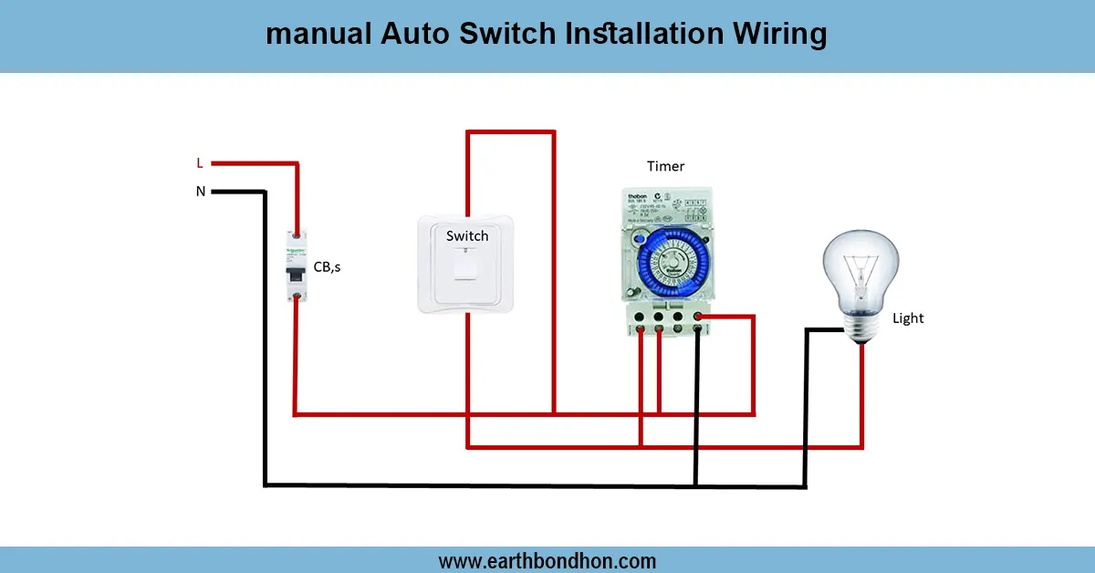
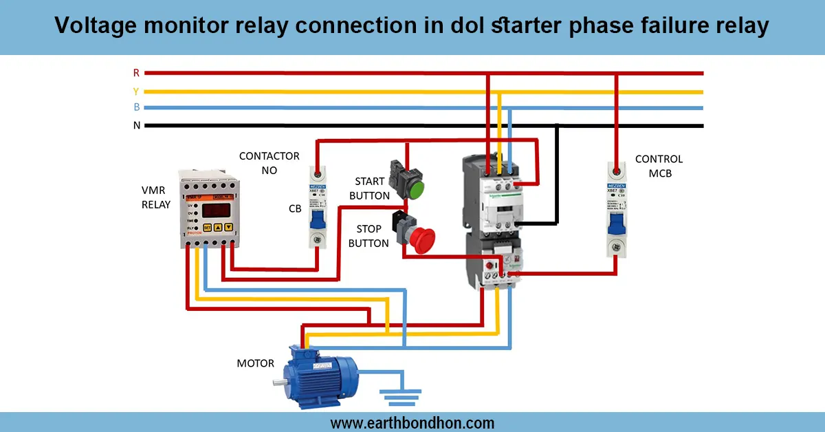
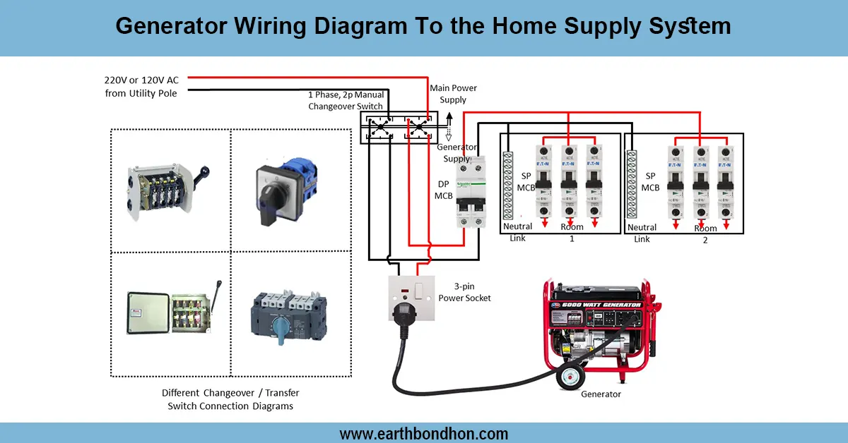
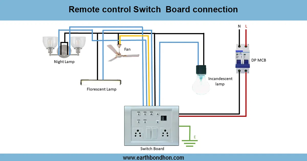
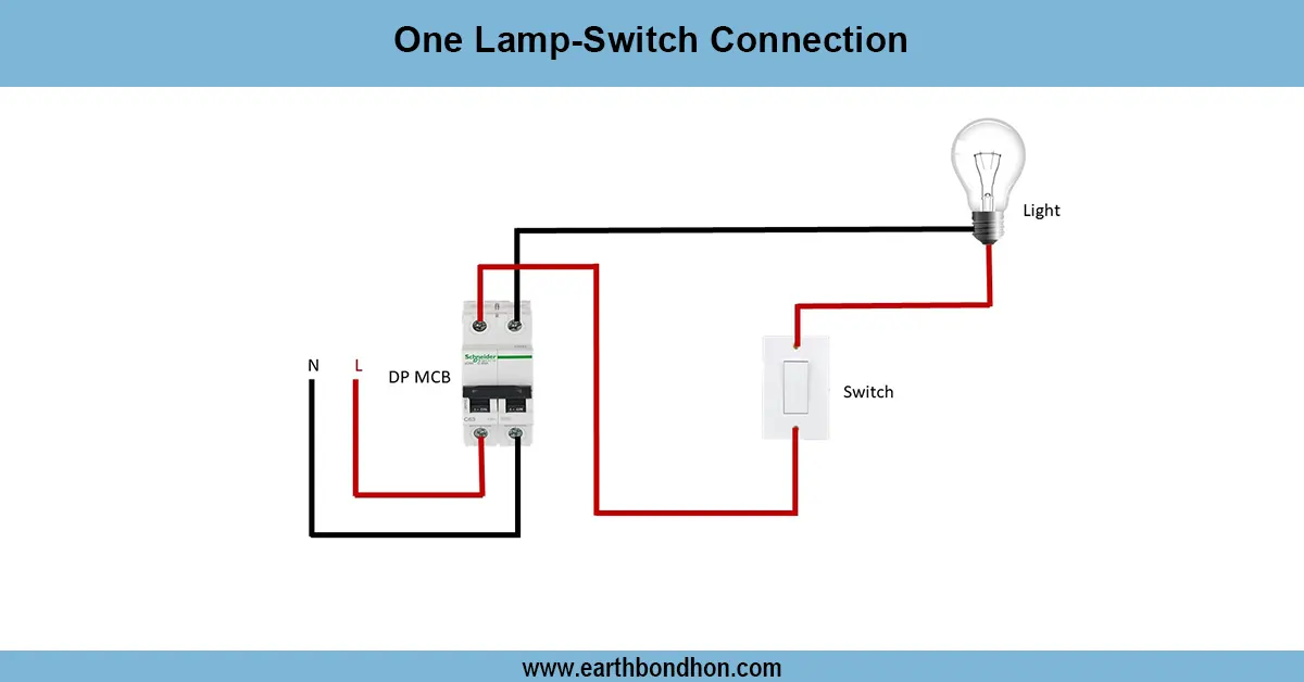
distribution board wiring diagram
Installation Checking In: Check the voltage delivered to the main switch, and check the individual MCB outputs to atester. Check the phase, neutral, and earth connections. Test RCCB trip Press the test button.
home distribution board setup
A distribution board system (DB) is the centre of an electrical installation where the incoming power supply is split into a number of circuits. It maintains a safe and dependable transmission of electricity to the various loads, which include lights, fans, sockets, and heavy appliances.
The DB is equipped with main switches, MCBs, RCCB/RCB, surge suppressors, bus, neutral/earth. The energy meter supplies are fed to the main switch or isolator, which is fed to the busbar supplying power to individual MCBs serving individual circuits.
A distribution board separates power in household circuits in single-phase, and load balancing between phases in three-phase in a distribution board. Such safety features as MCB to protect against overload/short circuit and RCCB to prevent earth leakage are critical.
Distribution boards are also common in residential, commercial, and industrial wiring systems to support higher protection, ease of maintenance, and effective power control.
A distribution board system is a system of distributing electricity in the main supply to various circuits with the help of MCBs, RCCB, and busbars, so that it can be safely and efficiently handled.
Work / Installation (Inputs → Outputs)
Input: Main supply → Energy Meter → Main Switch/Isolator → Distribution Board.
- Connect the incoming phase (L) and neutral (N) to the main switch.
- From the main switch, connect to the busbar inside the DB.
- Connect outgoing wires from the busbar to MCBs for each circuit (lighting, sockets, appliances).
- Install RCCB/RCB for earth leakage protection.
- Connect neutral wires to neutral bar and earth wires to earth bar.
Output: Each circuit receives independent protection and controlled power supply, ensuring safe operation of all electrical loads.
Testing & Final Adjustments
Test every circuit (lights, sockets, appliances) and make sure you have power. Three-phase DBs have balanced loads so that no phase is overloaded. Install MCBs of the appropriate rating (6A to 32A) as per the nature of the load.
Make sure that there are tight connections and labeling, and the correct size of the cable. Install surge protectors where there are frequent voltage spikes. A properly tested distribution board enhances the reliability of the system and minimizes the danger of a fire, as well as ensures user safety.