SSR Connection With Sensor Wiring Diagram
Learn SSR connection with sensor wiring, including control input, AC load, protection, and proper earthing for automated and safe switching applications.

SSR connection with sensor wiring
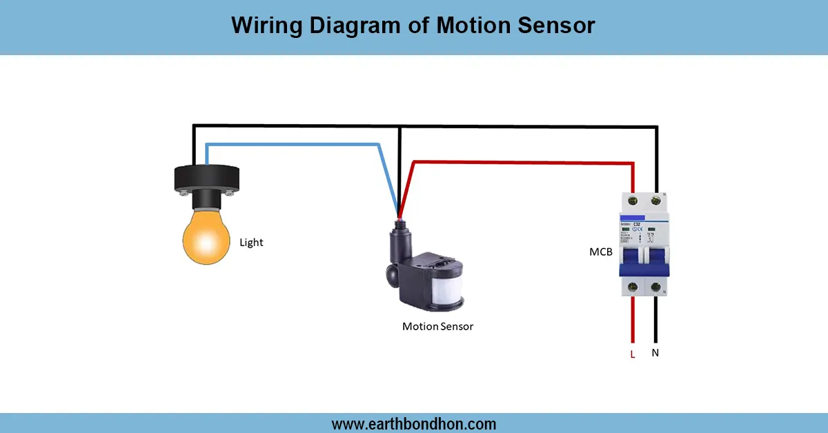
The connection between a sensor and an SSR is presented in an SSR wiring diagram; in this case, the sensor is the control input to an SSR, which completes an AC load with a safe and well-protected earthing switch.
sensor controlled AC load with SSR:
A Solid State Relay (SSR) is an electronic switching device that is used to drive AC loads with a low-voltage DC signal. SSRIs find extensive use in automation, temperature, and industry. The wiring is a sensor (temperature, proximity, or pressure) that is observed linked to the SSR control input. The SSR output terminals are connected to a load line that is supplied with the AC. Major AC supply is sent through protective devices such as a fuse or an MCB. The SSR control input should be properly poled, and the AC load terminals should supply the mains voltage. To be safe, metallic parts must be earhed. The wiring diagram indicates the following connections: sensor to SSR control to AC load to AC supply to protection to earthing. The adherence to the diagram guarantees the reliable switching, elimination of the electrical hazards, the elimination of the damages of the SSR and load, and the possibility of automated work based on the sensor readings.
Work & Installation (Input → Output,)
- Input Signal: DC voltage from sensor or controller connected to SSR control terminals.
- Protection: AC supply passes through MCB or fuse before connecting to SSR load terminals.
- SSR Output: Switches AC load (heater, motor, or lamp) according to control input.
- Sensor: Sends signal when a threshold is reached (temperature, pressure, or proximity).
- Load Connection: AC load connected to SSR output, turning on/off automatically.
- Earthing: Metallic parts and AC load grounded for safety.
- Output: Load operates automatically based on sensor readings, with safe SSR switching.
Such an arrangement guarantees efficient automated and safe functionality of AC loads with an SSR.
Testing & Final Adjustments
Once the wiring has been done, ensure that the sensor will send the appropriate DC signal to the SSR control input. Flip the AC power using the protective device. Test Test, by activating the sensor, whether the AC load goes on/off. Check all connections to ensure they are tight and well insulated, and of the correct polarity. Make sure that the earthing is continuous. Test cycles: Test various test cycles to verify that SSR is functioning properly and that it responds to load. Control sensor settings to the preferred control threshold. Correct testing eliminates the SSR or load damage that results as a result of wrong wiring or overcurrent. Label the SSR, sensor, load, and protection device so that they can be easily repaired. Using the wiring diagram will provide safe and automated switching of AC loads, extend the life of the SSR and load, and eliminate any electrical hazards of industrial or home automation.
Frequently Asked Questions - SSR Connection With Sensor Wiring Diagram:
What is an SSR?
A Solid State Relay is an electronic switch that controls AC loads using a DC input signal.
How is the sensor connected?
The sensor output DC signal connects to the SSR control input terminals.
What AC loads can SSR control?
Heaters, motors, lamps, and other AC appliances.
Is protection necessary?
Yes, use MCB or fuse to protect AC supply and SSR.
Is earthing required?
Yes, for safety and to prevent electric shocks.
Can multiple SSRs be used with one sensor?
Yes, if the sensor can handle multiple control inputs.
What voltage is used on SSR input?
Typically 3–32V DC, depending on SSR specifications.
What voltage is switched on the output?
AC voltage according to the load rating, commonly 220–240V.
How to test SSR operation?
Trigger the sensor and observe if the AC load switches correctly.
Why follow the wiring diagram?
Ensures safe, reliable, and automated switching of AC loads.