Single phase Meter Wiring Circuit Diagram
Learn single-phase meter switchboard wiring with MCB, DP switch, and energy meter connections for a safe and reliable home electrical setup.

electrical socket wiring
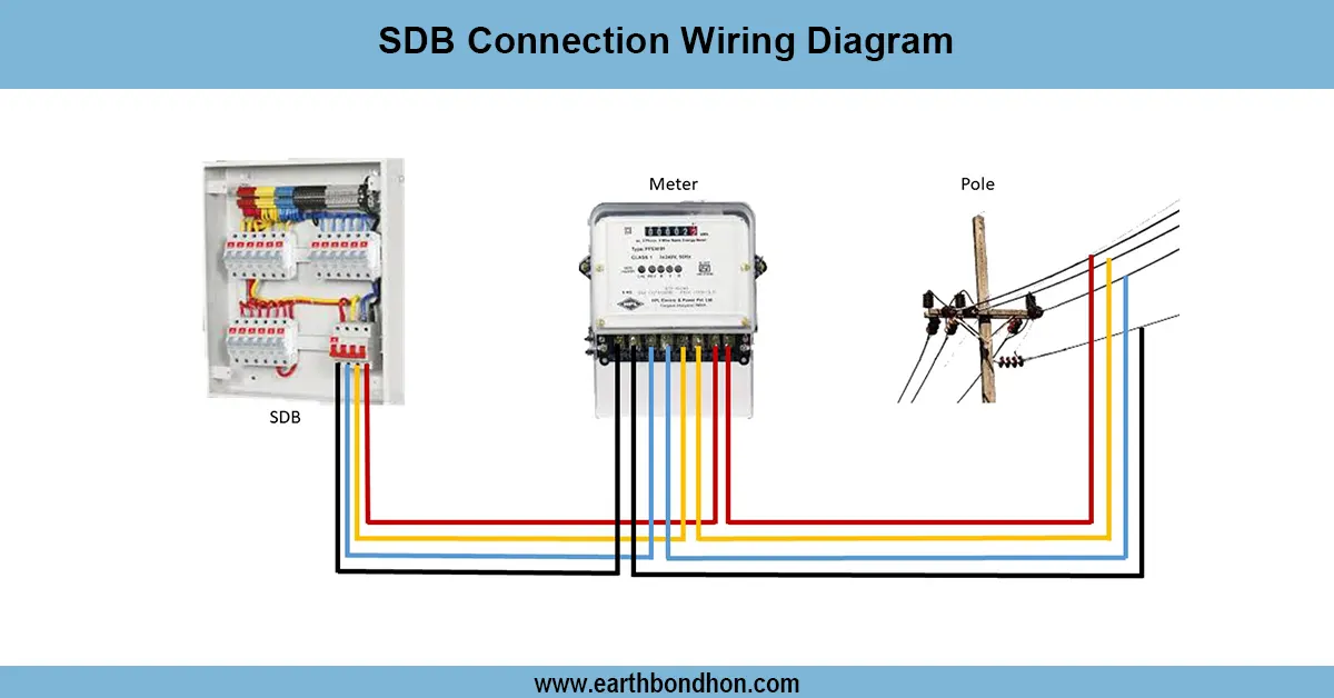
One stage of supply meter Wiring diagram illustrates the operation of the one phase meter switch board wiring passing through the utility supply into the energy meter, main DP switch/MCB, and then into sub-circuits through distribution board MCBs.
single phase meter wiring diagram:
One phase meter switch board diagram of wiring is the entire diagram of connecting the service line between the power supply and the home distribution system. Wires are then taken into the house, and the neutral line and incoming are then connected to the energy meter that measures the amount of electricity consumed. Based on the meter, the output wires are connected to the main switch or the DP MCB, which offers protection and can be used to isolate the phase and the neutral. The connections are then extended to sub-MCBs within the distribution board, in which each circuit serves a particular load including lights, fans, sockets, geysers, and air conditioners. Safety is also taken care of through proper earthing. Individual loads use an individual-rated MCB to avoid overloading. Should there be a fault or a short circuit, then the MCB trips immediately to safeguard it. Proper wiring provides safety in operation, secure distribution of electricity, and prevention of electrical effects in household use.
Work & Installation (Input → Output)
It starts at the stage of the incoming of the electricity provider and neutral lines. These lines are initially introduced to the energy meter, and they are used in the measurement of the consumption. Based on the meter, the phase and neutral are linked to the main MCB of DP, and both wires are disconnectable in case of danger. The output of the main switch is then fed to the distribution board, where several sub-MCBs are fitted to various circuits. The MCBs are used to protect specific load circuits of lights, fans, sockets, geysers, or air conditioners. Every load circuit is properly grounded to prevent electric shocks. The wiring is finished by the connection of the corresponding loads to the sub-MCB outputs. This installation is sufficient to distribute electricity in the house systematically and to protect it completely.
Testing & Final Adjustments
Following the wiring, it should be thoroughly tested. First, ensure that the main DP switch and MCBs are properly rated, as they should be based on the load requirement. Turn on the service supply and check the energy meter reading to make sure that the phase and the neutral are connected. Each sub-MCB must be testable one by one, i.e,. put on, and then the loads connected would be observed. The MCB is supposed to trip immediately in case it is overloaded, and this is evidence that the protection is working as it should. Earthing resistance also ought to be verified and maintained under 1 ohm in order to be safe. Measurement of voltage across each load point should be done to ensure that there is an appropriate distribution. The DP switch has to de-energize the phase as well as the neutral. All loose connections must be tightened, and cable insulation should be checked to prevent future faults. Once the tests are successful, label all the circuits (lights, fan, sockets, geyser, AC, etc.) to identify them easily. Last-minute refinements provide safe, dependable, and extended working of the domestic wiring system.