Motor Protection Circuit Breaker Wiring
Learn motor protection circuit breaker wiring to safeguard motors from overload, short-circuit, and phase failure, ensuring long motor life and safe operation.

electrical motor safety circuit
The wiring of the motor protection circuit breaker is designed to provide safe operation of the motor, so that the motor does not suffer due to overloading, short-circuit, or phase failure. It forms a necessary component of any motor control system.
motor protection circuit breaker wiring
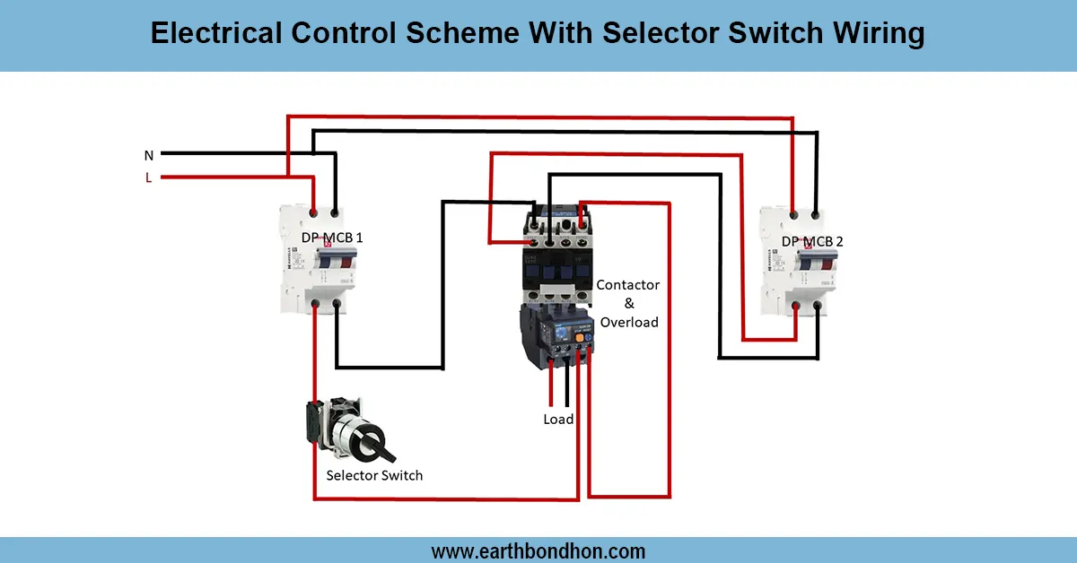
The use of motor protection circuit breakers (MPCB) wiring is necessary to protect motors against overload, short-circuit, and phase failure. The AC supply, be it three-phase or single-phase, goes through a circuit breaker or MPCB and then to the motor terminals. Other protective gadgets, such as fuses, overload relays, or contactors, can also be added to improve safety. Safe operation requires a neutral and earth connection. Correct wiring avoids burnout, electrical hazards, and downtime of the motors. The tests are performed by alternating the supply between ON and simulating overload or fault operation to verify that the breaker trips accordingly. This wiring is common in all types of industrial, commercial, and residential motors to enhance motor life and ensure dependable service.
Work & Installation (Input → Output Summary)
- ConnectAC supply to the input of the motor protection circuit breaker (MPCB).
- Connect the output of the MPCB to the motor terminals.
- Includeoverload relays or fuses if required for additional protection.
- Ensure proper neutral and earth connections.
- Switch ON the supply to test normal motor operation.
- In case of overload or short-circuit, the MPCB trips and disconnects the motor automatically.
Testing & Final Adjustments
- Verify all wiring: supply, MPCB, overload relay, motor terminals, neutral, and earth.
- Switch ON supply; check motor starts normally.
- Simulate overload or fault; confirm MPCB trips to protect the motor.
- Inspect neutral and earth connections for safety.
- Check the contactor operation if included in the circuit.
- Perform multiple trip-reset cycles to ensure breaker reliability.
- Ensure motor insulation and connections are intact.
- Verify proper labeling of the motor and breaker.
- Confirm no unusual noise, vibration, or heat in the motor.
- Document wiring, test results, and settings for maintenance.
Frequently Asked Questions - Motor Protection Circuit Breaker Wiring:
What is a motor protection circuit breaker?
A breaker that protects motors from overload, short-circuit, and phase failure.
Why is it necessary?
To prevent motor damage, electrical hazards, and downtime.
Where is it installed?
Between AC supply and motor terminals.
Can it protect against phase failure?
Yes, many MPCBs include phase failure protection.
Is neutral and earthing required?
Yes, for safe operation and grounding.
Can it be used for single-phase and three-phase motors?
Yes, wiring differs slightly based on supply type.
How to test the MPCB?
Simulate overload or fault conditions and verify breaker trips.
Does it replace overload relays?
No, but it provides additional protection along with relays.
Is it suitable for industrial motors?
Yes, it is widely used in industrial and commercial motors.
What happens when MPCB trips?
It disconnects the motor from supply to prevent damage.