
Extension Box Wiring
Learn extension box wiring connection diagram with step-by-step guide, safe installation, and testing for lights, sockets, and appliances at home or office.

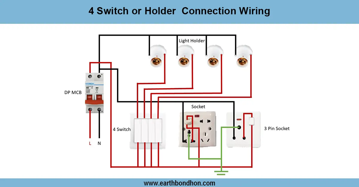
extension socket wiring connection
A wiring connection is an extension box that provides a safe distribution of electricity to a number of sockets. Phase, neutral and earth are well connected and the devices may safely be operated.
extension box installation diagram
An extension box wiring connection enables more than one device to be fed safely off the same supply. The wiring is done properly, so the extension box can carry electrical load without short circuiting. An extension box normally consists of live (phase), neutral and earth terminals. Supply phase is linked to the live, neutral to the neutral and earth to earth terminal. Electricity is distributed to all sockets in the box by internal wiring. Proper installation prevents overloading, sparking or electricity hazards. In homes, offices and workshops, extension boxes are usually used to power lights, fans, laptops, chargers, and other small appliances. After the wiring diagram, the wiring is reliable and passes the safety inspection.
Work / Installation (Inputs → Outputs)
- Input: Phase (line) and neutral from supply.
- Output: Multiple sockets connected through the extension box.
steps:
- Open the extension box and locate live, neutral, and earth terminals.
- Connect phase wire from supply to live terminal.
- Connect neutral wire from supply to neutral terminal.
- Connect earth wire from supply to earth terminal for safety.
- Internal wiring should connect all terminals to individual sockets.
- Close the extension box, ensure wires are insulated, and power ON to test each socket.
Testing and Final Adjustments
Check connections after wiring, ensure that they are tight and insulated. Check every socket using a small appliance to ensure that it works. Get earth connected to eliminate the possibility of an electric shock. Ensure that there are no exposed and loose wires. When a socket failing occurs, check the connection of the terminals once more. When the extension box is properly tested, it supplies the power to all the devices safely without overloading or sparking.