Single Line Diagram of panel Board
Learn exterior light wiring from the electrical panel, including switches, circuit breakers, protection devices, and load connections for safe outdoor lighting.

switch and breaker wiring diagram
Another example is external light wiring that is supplied by an electrical panel as a safe way of supplying power to outdoor lamps. Proper electrostatic coupling of breakers, switches, and earth guards to faults and permits valid outdoor lighting.
protective devices for exterior lights
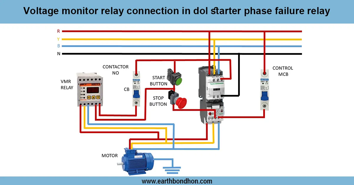
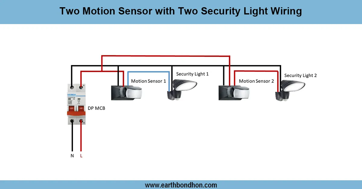
Outdoor light wiring- in a wiring diagram of electrical panels, the connection of the exterior lights is depicted in an overall way that is safe to the main supply. The installation consists of a main breaker, an exterior light circuit breaker, switches, protective devices, and light fixtures. The line wire of the panel passes through the breaker and through the switch to the lamp. The light has the neutral wire connecting straight off the panel. Connection with the ground prevents a failure of insulation. Secondary to this can be added automated operation surge protectors or timers. Quality wiring provides a safe operation, overloaded protection, easy service, and adherence to the electrical standards. Testing is done to verify continuity, operation of switches, operation of breakers, and proper earthing connection. This wiring is very common in residential gardens, street lights, commercial outdoor lighting, and industrial exterior installations.
Work & Installation (Input → Output Summary)
- Main Panel receives supply from utility or main breaker.
- Circuit Breaker dedicated for exterior lights protects against overload.
- Line Wire passes through switch to control light ON/OFF.
- Neutral Wire goes directly from panel to light fixture.
- Earth Connection from panel to lamp ensures safety against leakage or fault.
- Optional timer or sensor can automate light operation.
- Proper wiring ensures safe, reliable outdoor lighting with protection from electrical hazards.
Testing & Final Adjustments
- Verify all line, neutral, and earth connections from the panel to the exterior lights.
- Test circuit breaker operation by simulating an overload or short circuit.
- Operate the switch; light should turn ON/OFF correctly.
- Inspect earth connection for continuity and proper contact.
- Test optional timers or sensors for correct automation.
- Check insulation of wires for outdoor exposure.
- Ensure fixture mounting is secure and wiring is weatherproof.
- Test repeated switching cycles to confirm reliability.
- Confirm no flickering or voltage drop under load.
- Record test results and panel settings for maintenance.