single Phase Motor Control From 2 points
Learn single-phase motor control from 2 points with wiring diagrams, DP switch/MCB protection, safe operation, and step-by-step installation for home motors.

electrical socket wiring
The 2-point diagram of a single-phase motor control can be used to demonstrate how a motor can be operated with the control system at 2 points with correct isolation and safety with either 2 SPDT switches or a DP switch system.
single phase motor control wiring diagram:
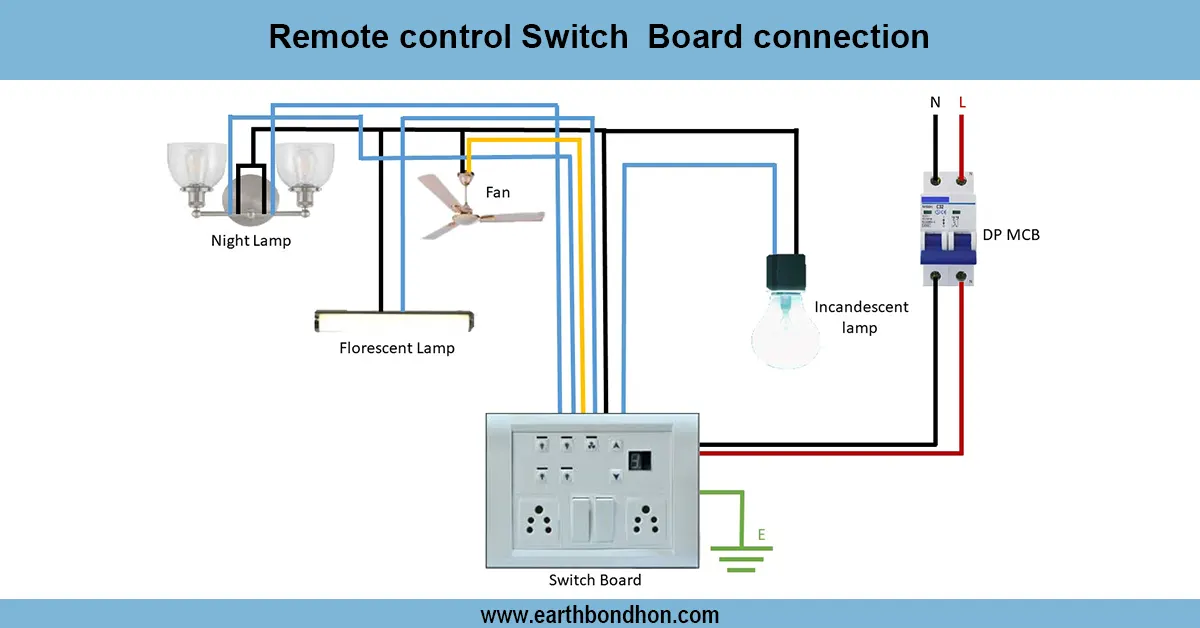
Two-point single phase motor control Two-point single phase motor control enables a motor to be operated at 2 points, usually with two two-way (two-way) switches (also called SPDT switches) or a DP switch array. It is widely applied in such applications as water pumps or ceiling fans, where a remote control of the motor is required. The neutral and the incoming phase are also connected by means of the main DP switch or MCB. The motor terminals are wired together as per the wiring diagram, and two control points are wired such that flipping the switch ON or OFF at either position either initiates or de-initiates the motor safely. Earthing is necessary in order to prevent shocks. This design enables a convenient operation and does not require physical access to the motor panel, and offers safety, flexibility, and safety of motor control in homes and small industrial facilities.
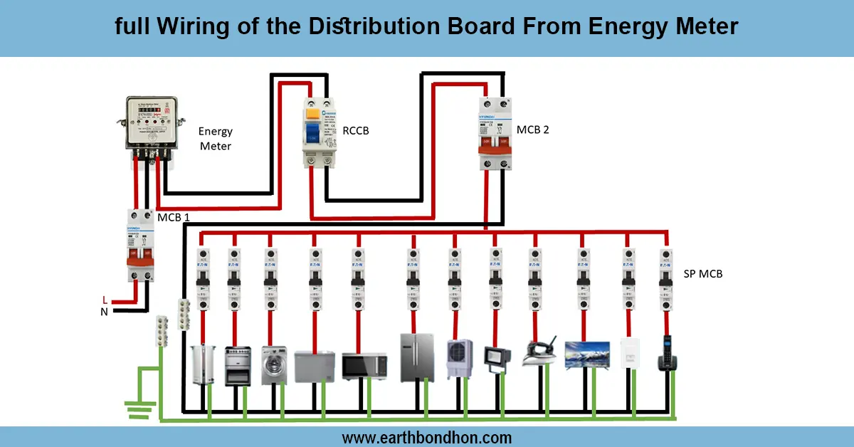
Work & Installation (Input → Output,)
- Input Supply: Phase and neutral wires from main supply.
- Main DP Switch / MCB: Provides protection and isolates both phase and neutral.
- Motor Terminals: Connect main winding to supply via control wiring.
- Control Points: Two SPDT switches or a DP switch arrangement allow ON/OFF control from two locations.
- Earthing: Motor frame and switches grounded properly.
- Output: Motor can be started or stopped from either of the two points safely.
This arrangement can guarantee convenient control and flexibility of the operations and safe control of the motor without having direct access to the motor.
Testing & Final Adjustments
Installation After installing, ensure that the DP switch or MCB is correctly connected to suit the motor load. Check each point of control separately: the motor should begin running when that control point is switched ON and cease when either of the control points is switched OFF. Make sure that the two switches are working properly without short-circuiting or reversing current. Check the voltage at motor contacts to ensure correct supply (220 V -240 V). Carry out the earthing connection in a proper manner to ensure safety. Check any wire endings that are tight and insulated. Mark both control points so that they can be identified easily. The system is also reliable in control of motor operation at two distinct locations, safe isolation, and protection against electrical faults after these checks.
Frequently Asked Questions - single Phase Motor Control From 2 points:
What is 2-point motor control?
It allows a single phase motor to be controlled from two separate locations.
Which switches are used?
Two SPDT switches or a DP switch arrangement are typically used.
Can it be used for water pumps?
Yes, it is commonly used for pumps, fans, and other household motors.
Is earthing required?
Yes, motor frame and switches must be properly grounded.
Can I use MCB instead of DP switch?
Yes, a DP MCB can isolate both phase and neutral safely.
How to wire the control points?
Use SPDT switches in a 2-way control circuit as per diagram.
Can motor run if one switch fails?
Yes, the other switch can still control the motor safely.
What is the supply voltage?
Typically 220V–240V single phase AC.
How to test after wiring?
Switch ON/OFF from both points and check voltage and MCB operation.
What is the advantage of 2-point control?
It allows convenient motor operation from multiple locations without accessing the motor panel.