single phase Motor Timer power pin Working
Learn single-phase motor timer power pin working with wiring diagram, showing how the timer relay powers the motor, DP switch/MCB protection, and safe operation.

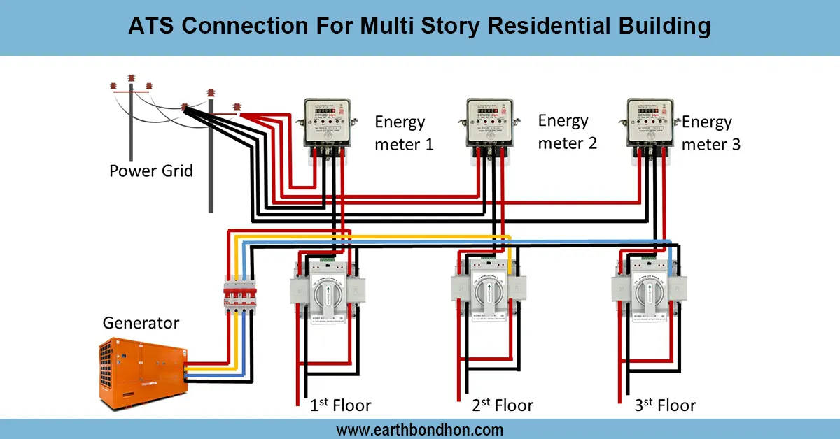
single phase motor with timer wiring
One phase of the motor timer power pin diagram depicts the way the timer relay directs the voltage to the motor starter coil to resolve the start and stop of the motor in a safe way.
single phase motor timer connection diagram:
Single-phase motor timer and power pin enable the user to connect the power pin to a timer relay, thus auto turning a motor on and off. The timer has a pin that allows the voltage to flow to the motor starter coil as per the time set. The neutral and the incoming stage are joined with a DP switch or an MCB to provide overload protection as well as safety. When the timer is activated, the power pin passes current to the starter coil, which supplies electricity to the motor. This is frequently applied in pumps, fans, or other single-phase motors when it is necessary to have it automatically operated. Correct wiring will have the timer relay, starter coil, and motor coordinated with each other without any manual adjustment. The frame of the motor, timer, and starter panel must be grounded to prevent accidents. Proper installation will avoid electrical faults, overloading, and will also have reliable operation of the motivators based on the settings of the timer.
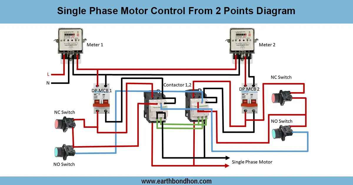
Work & Installation (Input → Output,)
- Input Supply: Phase and neutral from the main line.
- DP Switch / MCB: Isolates supply and protects against overload and short circuits.
- Timer Relay: Receives power through the main supply and controls the motor starter coil via the power pin.
- Motor Starter Coil: Energized when the timer activates the power pin, switching ON the motor.
- Motor Terminals: Connected to starter output according to wiring diagram.
- Earthing: Motor frame, timer, and starter panel grounded for safety.
- Output: Motor operates automatically according to timer settings; starts when the power pin activates the starter coil and stops when deactivated.
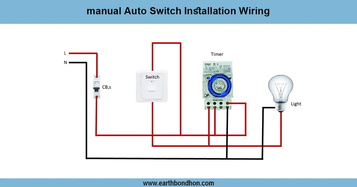
Testing & Final Adjustments
Wire. Once wired, all connections must be tight and insulated. Change the DP switch or MCB and set the timer to some test time. Ensure that the timer relay switches the power pin and starts the starter coil, and the motor will start automatically. At the expiry of the preset time, the power pin discharges the starter coil, and the motor ceases. Measure voltage on motor terminals (220 V -240 V) to ensure proper functioning. Make sure that earthing connections are firm and working. Check to see if there is abnormal noise, vibration, or overheating. Connect loose connections and label the timer, power pin, starter, and motor terminals so that they can be identified easily. These measures will make the motor reliable, the timer good, and the system free of overload or electrical risks.