Protection Relays used in Substation
Learn how 3-phase line electric protection relays work, their types, wiring connections, and importance in protecting motors, transformers, and power systems.

3 phase protection relay types:
A 3-phase line protection relay is used to protect electrical systems, and it checks faults that include overcurrent, earth fault, and unbalance. It shuts down a circuit breaker to avert destruction.
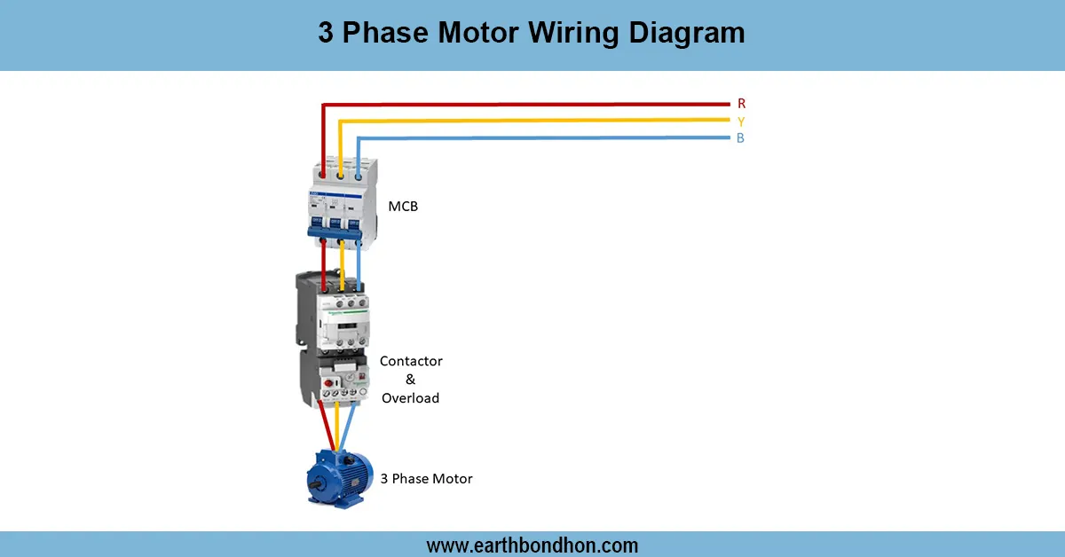
3 phase motor protection relay wiring:
Three-phase line electric protection relay is a vital equipment employed in the protection of the electric systems against faults, including overload, short-circuit, earth fault, phase failure, and unbalance. Continuous checks of the 3-phase current and voltage are done by relays, and in case of any abnormalities, relays send a trip signal to the circuit breakers so that the supply is disconnected. They are commonly classified as overcurrent relay (OCR), differential relay, distance relay, earth fault relay, under/over-voltage relay, and thermal overload relay. During the wiring part of the project, the relay is linked with the CTs (current transformers) and PTs (potential transformers) to measure the parameters. It next switches the breaker coil to switch the line when it is needed. These relays are common in motors and transformers, distribution panels, and industrial systems. Selection and wiring of 3-phase electrical networks. Protection relays are selected and wired properly to provide safe, reliable, and uninterrupted operation.
⚡ Work & Installation (Input → Output):
The circuit breaker and the 3-phase supply line are fitted with the protection relay. CTs (current transformers) and PTs (voltage transformers) are the inputs of the signals, which measure real-time voltage and/or current. These signals are processed by the relay and, in the event of abnormal conditions such as overcurrent, phase loss, or earth fault, a signal to open the breaker coil is transmitted by the relay. The faulty line or equipment is then disconnected by the breaker to prevent damage. Practically, OCRs are connected to currents of loads, earth fault relays to leakage to ground, a nd differential relays to input-output current in transformers. The wiring has provided proper monitoring and relay output contacts to breaker trip coils. This is done to ensure that faulty circuits are isolated quickly without causing a crash to the system.
Testing & Final Adjustments:
Wired relays should be tested and checked. Start with secondary injection testing, in which fault current is simulated and the response time of the relays is tested. Make sure that the relay closes the breaker in the measured time. Program pickup current, time delay, and earth fault sensitivity settings to suit system requirements. Perform primary injection testing to ensure that the CT/PT connections are correct and also ensure that the relays operate under load conditions. Phase sequence and unbalance protection. Phase sequence is tested by disconnection of a phase and observing the behavior of a relay. Unbalanced protection is tested by the disconnection of a phase and observing the system of a relay. The last fine-tuning is to ensure that relays are delicate enough to pick up faults but are not susceptible to variations in normal loads. Regular maintenance and testing of the relays ensures the reliability in the long run for the protection of 3-phase systems.
Frequently Asked Questions - Protection Relays used in Substation:
What is a 3 phase protection relay?
It is a device that protects electrical systems by detecting faults and tripping breakers.
Which faults can a protection relay detect?
It detects overcurrent, earth fault, overload, phase failure, and unbalance.
How is a protection relay connected?
It is connected via CTs and PTs to monitor current and voltage, with output to breaker coils.
What is the difference between OCR and EFR?
OCR detects overcurrent while EFR detects leakage current to earth.
Where are protection relays used?
They are used in transformers, motors, distribution boards, and substations.
What is differential protection relay?
It compares input and output currents of transformers or generators to detect faults.
Why is relay testing important?
It ensures correct operation and prevents false tripping or failure to trip.
What is primary injection testing?
It is applying real current to CTs and checking relay operation with actual load.
What happens if relay fails?
If relay fails, the breaker may not trip, causing equipment damage or fire risk.
Can digital relays replace electromechanical ones?
Yes, modern digital relays are more accurate, compact, and multifunctional.