

Window AC wiring
Detailed wiring diagram for window AC units covering power connections, thermostat wiring, compressor, fan motor, and safety components for safe operation.
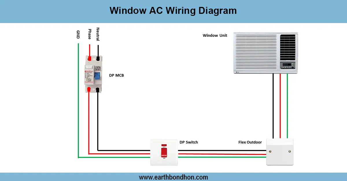
window AC electrical connections
A window air conditioning wiring diagram would show all connections between power and control wiring to interconnect compressor, fan motor, thermostat and safety devices so that the air conditioner can be efficiently and safely operated.
Formula & Table Summary:
Basic connections:
Power (L, N, E) → Thermostat → Compressor & Fan Motors
Capacitor: Connected in parallel to motors for starting torque.
Overload Protector: Series with compressor to prevent damage.
Thermostat: Switches compressor and fan ON/OFF based on temperature.
Safety: Proper earthing and fuse protection required.
| Component | Connection | Notes |
|---|---|---|
| Power Supply | Live, Neutral, Earth to unit | 230 V AC typical |
| Thermostat | Switches compressor/fan circuits | Temperature control |
| Compressor Motor | Powered via thermostat & overload protector | Includes start/run capacitors |
| Fan Motor | Wired parallel with compressor with capacitor | Circulates air inside unit |
| Overload Protector | Series with compressor motor | Protects motor from overheating |
window air conditioner wiring
The wiring diagram of window AC displays how the electric power line should be connected inside a common window air conditioner. It consists of power supply wiring (live, neutral and earth), Thermostat wiring, compressor motor wiring, fan motor wiring, overload protectors wiring and capacitors protection. The interpretation of this diagram assists in both installation and troubleshooting and repair requirements as it will show clearly the way each component is wired and regulated. The compressor and fan motors are fed by the power supply and the thermostat adjusts the operation of the two based on temperature setting. Capacitors aid in starting and running of motors. The types of safety devices are overheat and electrical faults. The wiring configuration will provide effective cooling and safety of the user.
AC installation wiring
| Temperature Setting | Thermostat State | Compressor | Fan Motor |
|---|---|---|---|
| Above Set Point | OFF | OFF | OFF |
| Below Set Point | ON | ON | ON |