2 Way light switch diagram
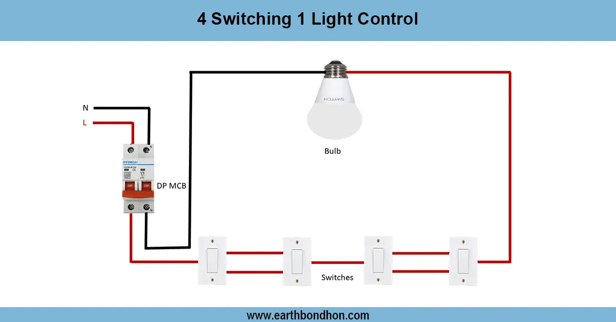
Detailed wiring diagram showing two two-way switch connection with a light circuit for controlling a single light from two different locations.

two way switch installation
A two way switch wiring diagram indicates the connection of two switches and one light so that the light could be controlled more than one way without reference to location of either switch by using traveler wires and making proper connections.
Two Way Switch Wiring Summary:
Components: Two SPDT switches, one light fixture, live (L), neutral (N), traveler wires.
Connections: Live supply → Common terminal of Switch 1; traveler wires connect the two switches; light connects to common terminal of Switch 2 and neutral line.
Operation: Toggling either switch changes the circuit state, turning light ON or OFF.
Safety: Ensure power is off before wiring, and use correct wire ratings.
| Terminal | Connection | Function |
|---|---|---|
| Switch 1 Common (C1) | Connects to Live supply | Input power |
| Switch 1 Travelers (T1, T2) | Connect to Switch 2 travelers | Carry switching paths |
| Switch 2 Common (C2) | Connects to Light fixture | Output to load |
| Light Fixture | Connects to Neutral | Completes circuit |
two way switch schematic
Light Circuit two way switch connection enables you to switch on a solitary light fitting through two unique switches. This is usually installed in corridors, stairways as well as big rooms. The electrical work includes the two SPDT (Single Pole Double Throw) switches where the traveler sets of wires and a load set of wires are connected to a lamp fixture. There is one switch that is linked to the live supply, and one light which is linked to the neutral line. The circuit is either completed or broken by flipping either switch, either turning the light ON or OFF. Being aware of this wiring diagram proves beneficial in installation and troubleshooting, which are also safe and effective control of lighting in more than one location.
two way switch connection diagram
| Switch 1 Position | Switch 2 Position | Light Status |
|---|---|---|
| Up | Up | OFF |
| Up | Down | ON |
| Down | Up | ON |
| Down | Down | OFF |