


Simple House wiring diagram
Learn house wiring with a single-phase energy meter diagram, input-output supply, MCB, DB, and safety steps explained with a proper connection guide.
house wiring single phase energy meter
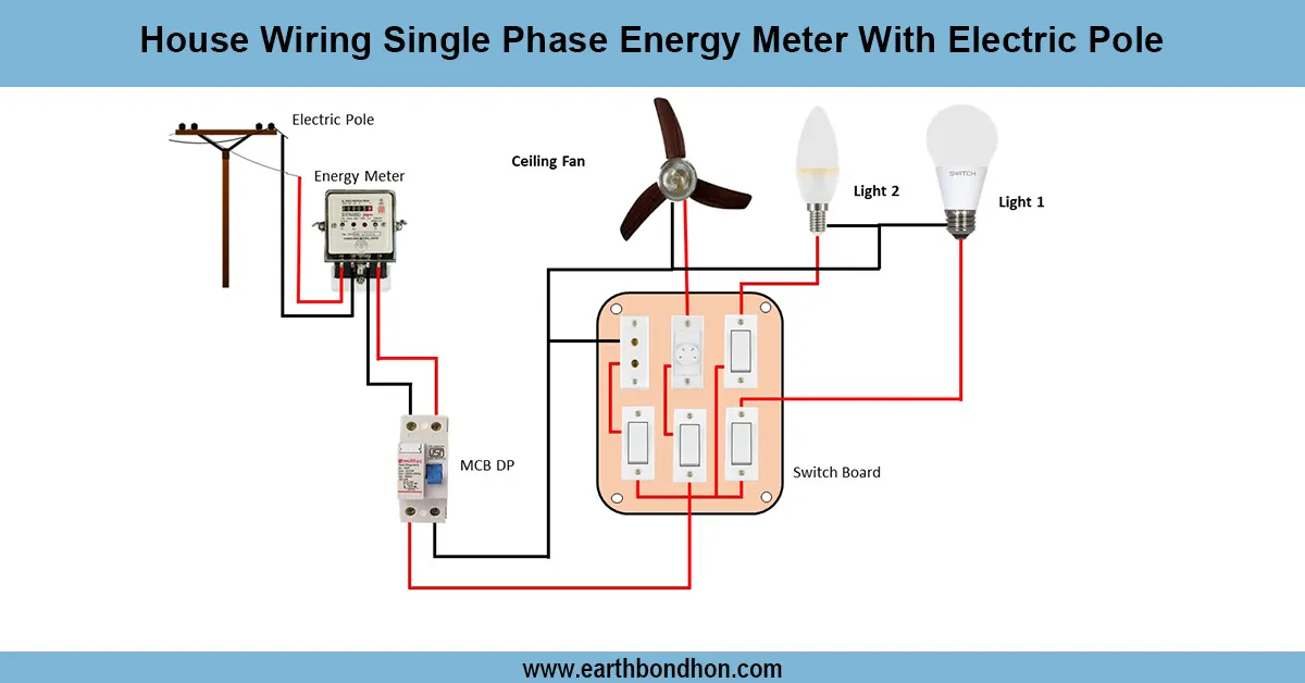
House wiring single-phase energy meter diagram. This provides the utility phase and neutral supply connected to the meter and then feeds out to the MCB, D, B, and household circuits.
single phase meter connection diagram
Single-phase house wiring demonstrates energy flow into the house through the main supply line, through the energy meter, and into various domestic circuit breakers. Phase and neutral wires of the utility service would be linked to the input terminals of the energy meter. The phase wire is taken on the output side through the main switch/MCB to the distribution board (DB), and the neutral wire is connected to the DB. Out of the DB, lights, fans, sockets, and appliances are fed on individual circuits. Earthing must be done properly to prevent electric shocks. Properly installed wire size, insulated connections, and protective devices can protect the electrical system and ensure long life. This is the generally used wiring diagram of a residential single-phase system.
Work / Installation (Inputs → Outputs)
The utility (phase and neutral) supply goes into the house and across the energy meter input connections. The phase wire exits the meter on the output side to the main switch or MCB, and feeds the distribution board (DB). The meter has a neutral wire that directly leads to a DB. The DB also splits the power into lighting, fans, and socket circuits. Individual MCBs protect each circuit. To achieve safety, the earthing line of the main earthing system is connected to the DB and then extended to every room. The installation must be done according to correct electrical standards and with standard copper wire, and all connections should be firmly secured.
Testing & Final Adjustments
Once wiring is done, we test to ensure that all works safely. Check all connections with a tester - phase, neutral, and earth should be ascertained. Resistance to the current flow of the wires before energizing. Turn on the supply and test the main switch and separate MCBs. Make sure that loads such as lights and fans are turned on to check the proper wiring. When using appliances, make sure that the energy meter is showing the correct readings. Test RCCB/MCB tripping is used to confirm overload protection and leakage protection. Loose connections must be stiffened, bare wires covered, a nd the DB cover properly closed. Lastly, label each circuit (e.g., Lights, Sockets, Fans) so that it can easily be maintained. Single-phase house wiring is safe and reliable with good adjustments and testing.