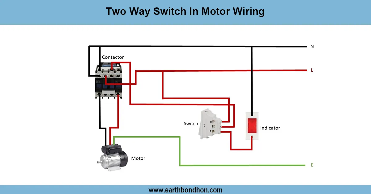
3 Switch 1 Light Wiring Diagram
Learn how to control one light using three switches with step-by-step wiring diagrams, circuit explanation, and real-life application tips for efficient electrical setups.

3 switch one light wiring
A 3 switch 1 light wiring diagram is the one that the most frequently applied to staircases, hallways, or other big rooms, where one light source should be controlled from more than one point. This wiring involves two 4-way switches and a center (4-way) switch. Since electrical interconnections are more risky and uncomfortable in a household or office setup, the correct usage of this circuit is the key to safety, ease of use, and low power consumption.
Wiring Formula Summary:
- Switch A = 2-way
- Switch B = Intermediate (4-way)
- Switch C = 2-way
- Live wire → Switch A → B → C → Light → Neutral
intermediate switch wiring diagram
The practice is that with three switches, each controlling one light, each switch is operated by one or more of up to three of the switches, usually two 2-way switches and one intermediate switch. It is ideal when you have long corridors or staircases or even large rooms where having several access points to turn the light ON/OFF is required. The simple concept is to run the line and neutral cables through the switches so that it makes a path, which flips the condition of lights based on the combination of the switch settings. Such an arrangement enhances conducive use by respective users and saves energy in shared space.
corridor light with 3 switches
| Switch A | Switch B (Intermediate) | Switch C | Light State |
|---|---|---|---|
| UP | Straight | UP | ON |
| DOWN | Cross | DOWN | OFF |
Frequently Asked Questions - 3 Switch 1 Light Wiring Diagram:
What is a 3 switch 1 light setup?
It allows controlling one light from three different switches using two 2-way and one intermediate switch.
Where is this circuit used?
Typically used in staircases, long hallways, or rooms with multiple entry points.
What type of switches are required?
Two 2-way switches and one intermediate (4-way) switch.
Is it safe to use this wiring at home?
Yes, if installed correctly following safety guidelines.
Can I use smart switches in this setup?
Yes, compatible smart switches can replace traditional ones.
How does the intermediate switch work?
It redirects current paths without breaking the circuit.
Does this setup consume more electricity?
No, it only controls the same light using multiple switches.
Can I wire it myself?
Yes, if you understand wiring basics and take precautions.
What color wires are used?
Live, neutral, and two travelers (usually brown, black, grey depending on standard).
Do I need a neutral at every switch?
Neutral is only needed at the light point, not all switches.