

2-way Switch Control in 3-Phase Motor
Learn how to use a 2-way switch control for a 3-phase motor to operate it from two locations, including wiring diagrams and safety tips for reliable control.
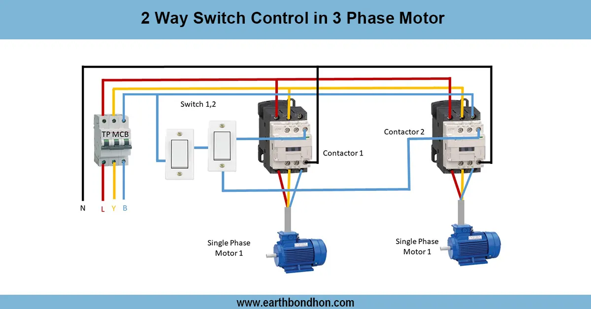
3 phase motor two location control
Controlling 3 phase motor motors with 2 way switches can enable start/stop capability at two locations by wiring switches in series on the control circuits but leaving the main power terminals fixed permanently to safely control multi-point.
2 Way Switch Control Wiring Summary:
Power Lines: Fixed 3 phase supply to motor terminals
Control Circuit: Two 2 way switches connected in series with starter coil
Operation: Either switch toggles motor start or stop
Safety: Interlocking prevents simultaneous conflicting commands
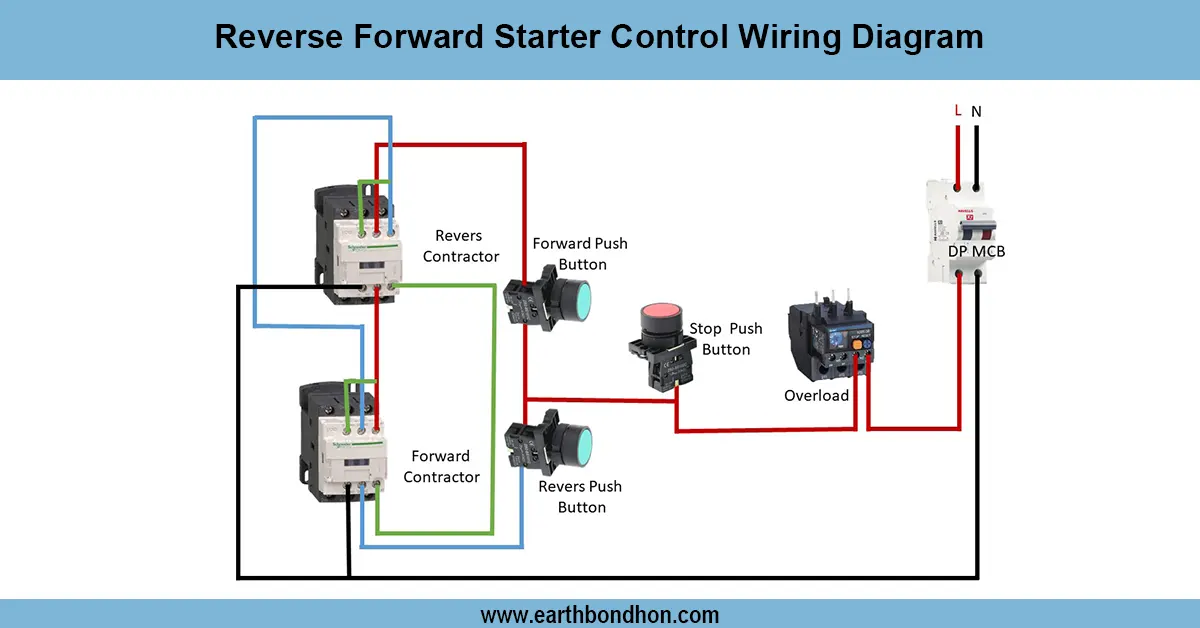
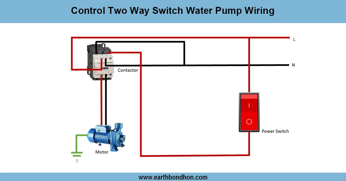
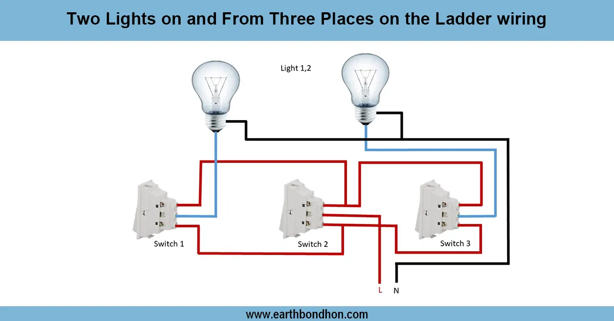
2 way switch wiring diagram
A 2 way switch type control on a 3 phase motor application will enable the raising and lowering of the motor in two different positions thus suitable when large installations are involved, such is the case with conveyors or hoists. This wiring entails two switches that line the motor in such a way that when one switch toggles it switches the operational state of another switch. The switches regulate the starter coil circuit which turns on or turns off the motor. The power and motor wiring are fixed with the control circuit consisting of 2 way switches (also called the SPDT or toggle switch) and interlocking contactors that provide safety. Such an arrangement permits control operation of the motor at multiple points in a safe manner, and without resulting in power system faults or unintended simultaneous operation. Understanding the wiring layout and even safety interlocks is recommended to prevent destruction of a motor or control equipment.
2 way control circuit
| Component | Function | Description |
|---|---|---|
| 3 Phase Power Supply | Provide motor power | L1, L2, L3 connected to motor terminals |
| Starter Coil | Control motor ON/OFF | Energized via 2 way switches |
| 2 Way Switches | Toggle motor control | Allow control from two separate locations |
| Interlocking | Prevent conflicting signals | Ensures safe motor operation |