
4 Gang Switch 4 Bulb Wiring
Learn how to wire a 4-gang switch to control 4 individual bulbs. Ideal for multi-light room setups with simple step-by-step wiring guide and diagram.

multiple light switch wiring
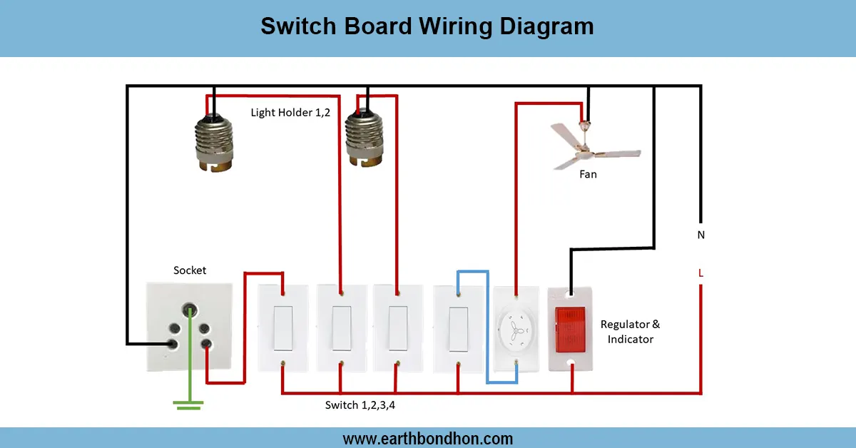
The use of a 4 gang 4 bulb wiring diagram shows how it is possible to switch on / switch off four light bulbs with the use of four separate scitches controlled independently. The switches should be connected in series with each being connected to one bulb, and should be on the same phase and neutral. This is a more independent control of every light and could be used in a switchboard of rooms, hallways and offices.
Wiring Formula Summary:
- Total Power: Ptotal = P₁ + P₂ + P₃ + P₄
- Current per Bulb: I = P / V
- Voltage: V = 220V AC (Standard)
- Connection: Each switch in series with its bulb
4 gang switch wiring
One 4 gang switch 4 bulb wiring will enable an individual bulb to be turned on/off by a switch. It is a widely used wiring in homes and businesses whereby the users are in need of controlling individual lights. One way has all the switches hooked up in series with a bulb and one of the lines is live. This layout offers safety, accessibility in maintenance, and economical consumption of energy.
4 Gang Switch 4 Bulb Wiring
| Switch | Bulb | Power (W) | Voltage (V) | Current (A) |
|---|---|---|---|---|
| Switch 1 | Bulb 1 | 60 | 220 | 0.27 |
| Switch 2 | Bulb 2 | 60 | 220 | 0.27 |
| Switch 3 | Bulb 3 | 60 | 220 | 0.27 |
| Switch 4 | Bulb 4 | 60 | 220 | 0.27 |
Frequently Asked Questions - 4 Gang Switch 4 Bulb Wiring:
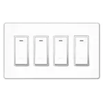
What is a 4 gang switch?
A switch panel with 4 individual switches to control 4 separate loads.
Can I use 1 gang box for 4 bulbs?
Yes, with a 4 gang switch and proper wiring.
How many wires for 4 switch control?
Each switch needs live-in, and live-out to each bulb.
What size breaker for 4 bulbs?
A 6A breaker is typically sufficient for low wattage bulbs.
Can I use LED bulbs in this wiring?
Yes, LED bulbs are compatible and energy-efficient.
Is neutral wire needed in switches?
Not in basic switches, only live wire passes through switches.
Which wire goes to common terminal?
Live wire connects to the common terminal.
Are all bulbs controlled separately?
Yes, each switch operates one bulb independently.
What color wire is live?
Usually red or brown for live wires.
Can I extend this to more switches?
Yes, use a 5 gang or 6 gang switch with additional wiring.