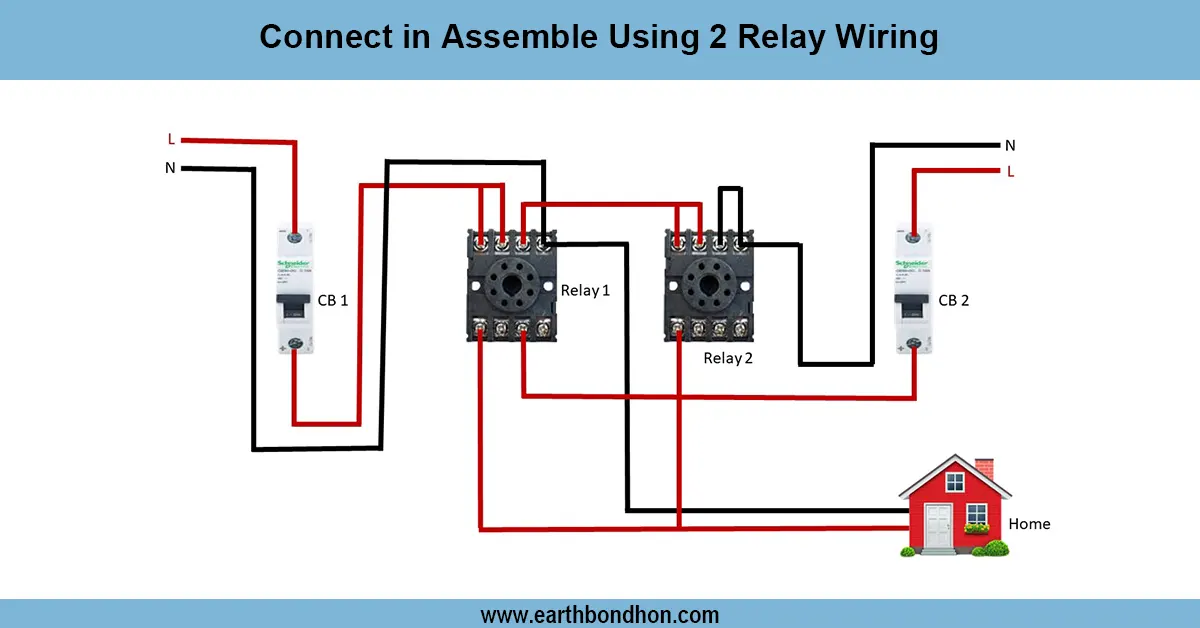


IPS Connection Diagram
Learn single-phase full house IPS wiring to supply uninterrupted power to lights, sockets, and appliances using battery backup with proper safety measures.

inverter wiring single phase
Single-phase full-house IPS wiring involves being supplied by battery backup and provides constant power to all circuits in the home. When properly connected to the distribution board, safety, reliability, and efficient load management are achieved.
full house UPS wiring diagram
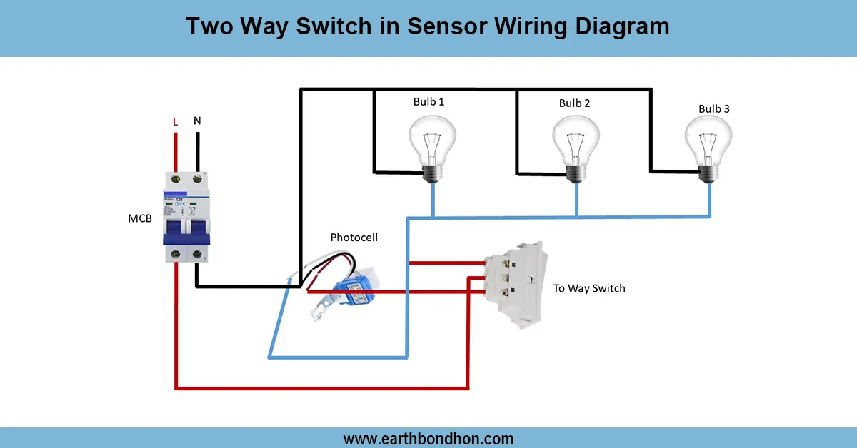
One single-phase full house IPS (Inverter Power Supply) wiring is the one that guarantees a continuous electricity supply in a home. The IPS transforms the battery DC power to AC, which is used in lighting, sockets, fans, and appliances in case of a power outage. The wiring will connect the IPS output to the main distribution board (DB), either using an automatic changeover switch or a manual switch. The inverter input is connected to the battery, and the inverter output is connected to the DB. The branch circuits of each of the DBs are guarded with MCBs or fuses. The earthing and insulation are done properly. Wires have to be color-coded: phase (red/brown), neutral (blue/black), earth (green/yellow). Correct sizing of cables, MCBs, and IPS capacity in total load is under the installation. Testing entails testing automatic switching, inverter performance, load supply, and battery performance. The labeling of the circuits can be used to make the home electrical system easy to maintain and to work safely.
Work & Installation Summary
- Switch off main supply before installation.
- Mount the IPS unit near the main DB.
- Connect batteries to IPS input terminals.
- Connect IPS AC output to the DB via automatic or manual changeover switch.
- Wire branch circuits from DB to lights, sockets, and appliances.
- Install MCBs or fuses for each circuit for protection.
- Ensure proper phase, neutral, and earth connections throughout.
- Label all circuits for maintenance.
- Test inverter operation, battery supply, and automatic switching.
- Verify safe operation under full house load full house load conditions.
Testing & Final Adjustments
- Check all electrical connections are secure and insulated.
- Verify phase, neutral, and earth wiring at DB and IPS.
- Test automatic changeover from mains to IPS and back.
- Check each branch circuit branch circuit for proper voltage and load supply.
- Inspect MCBs and fuses for correct operation.
- Ensure battery voltage, connections, and capacity match IPS requirements.
- Test inverter output under full load to confirm stability.
- Check appliances and lights for normal operation.
- Inspect wiring for exposed conductors or loose terminals.
- Document wiring layout, battery rating, and IPS settings for future reference.