
single phase pump wiring Diagram
Learn control one-way switch water pump wiring diagram with input-output connections, safe installation, and testing guide for smooth pump operation.

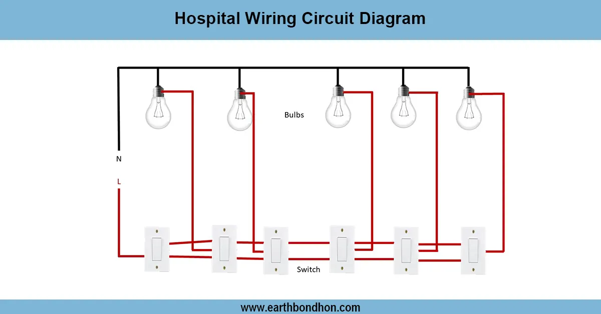
control one way switch water pump wiring
A control one-way switch water pump wiring gives the ability to use the pump in two places by passing the live line through both switches, and neutral through one switch.
one way switch water pump connection diagram
A control one-way switch water pump wiring diagram is a diagram of a water pump with two switches that can control one water pump from another position. The system can be applied in houses, farms, and buildings where ON/OFF control is needed at two locations and where it is convenient to do so, like near the pump and in the house. The phase wire is passed through the switch, with the neutral wire directly connected to the pump. With either switch, the connection can be altered, though, which means that the pump can be turned ON or OFF at either end. This wiring is safer, convenient, and efficient. Proper earthing, good quality switches, and correct wire gauge guarantee good performance and service life of the pumps.
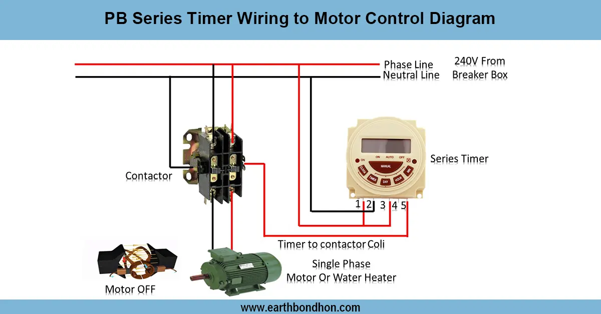
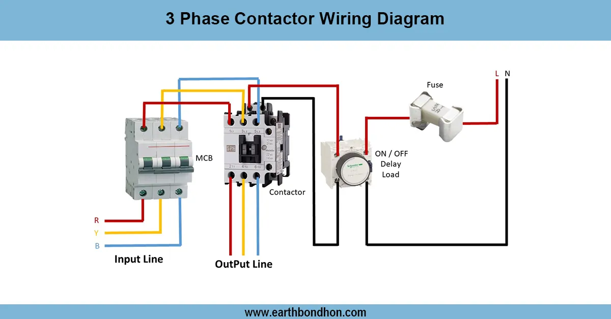
Work / Installation (Inputs → Outputs)
The phase of the main supply in this setup is passed first to the common terminal of switch 1. There are two wires with a traveler in them between switch 1 and switch 2. Switch 2 has one common terminal, which is connected to the live terminal of the pump. The neutral supply is connected directly to the pump motor. This installation allows you to switch the pump ON or OFF at either of the switch locations. Installation will require strong insulated wires and position switches in secure, accessible locations. Make proper connections between the travelers, since improper wiring will not allow it to work. Wiring when the power is on should always be avoided, and local electrical codes should be followed.
Testing & Final Adjustments
Wire connected, turn ON the main supply and operate the two switches separately. Either of the switches should make or break the pump. Check all switch combinations to check working. Check the traveler wire connections between switches in case the pump does not react properly. Check the circuit with respect to loose connections, overheating, or sparks. Make sure that the pump is properly earthed to protect the motor. Check for live voltage at the pump when turned ON with a tester. Name the switches (e.g., Pump Control - House and Pump Control - Outdoor). Perform several ON/OFF cycles in order to have a durable and reliable product. A last check ensures the effective and safe functioning of the water pump.
Frequently Asked Questions - single phase pump wiring Diagram:
What is a two way switch for water pump?
It allows a pump to be controlled from two different switch locations.
Where is two way pump wiring used?
In houses, farms, and buildings for convenient ON/OFF control of pumps.
How does two way switch wiring work?
Phase runs through two switches while neutral connects directly to the pump.
Which wire goes directly to the pump?
The neutral wire connects directly to the pump motor.
Can I control pump from two places?
Yes, with two way switch wiring, you can operate from two locations.
What is the common terminal in two way switch?
The terminal where input or output phase is connected.
What are traveler wires?
Two wires connecting the two switches to change the path of current.
Is earthing required for water pump?
Yes, proper earthing protects the motor and ensures user safety.
Can two way switch be used with motor?
Yes, it is commonly used to control water pump motors.
What safety precautions should I follow?
Turn off main power, use correct wire gauge, and ensure tight connections.