Auto timer for Water Pump
Learn the wiring of a fully automatic water level controller for pump operation, including float switches, relay, MCB, and indicators for safe, automated water management.

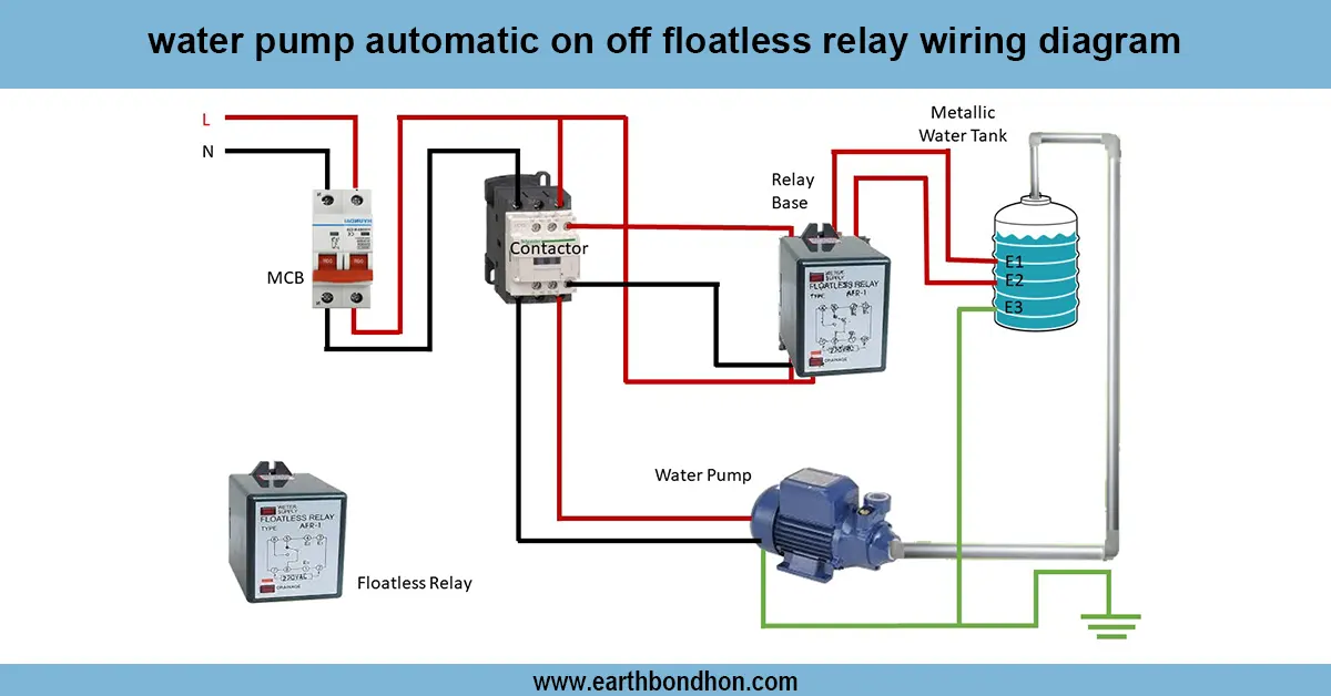
water tank level controller diagram
Fully automatic water level controller. A fully automatic water level controller is an automation of the pump, with float switches and a relay. The correct wiring will also make sure that the pump will activate when the water is lo,w and then it will switch off when the tank is full to prevent overflowing and dry running.
MCB and water level switch wiring
Fully automatic water level controller wiring describes the installation of wiring of a water pump to an automatic control system of float switches or level sensors. Main MCBs to ensure overload protection have the AC line passing through them. The upper, lower, and optional middle-level float switches in the tank are connected to a controller circuit (typically containing a relay) to which they provide input. When the water level goes lower than the lower float, the relay will activate the pump to be switched on. The relay is used to deactivate the pump when the water level reaches the upper float to avoid overflow. The indicator lights indicate the pump is ON or OFF and the level of the water. Proper wiring will provide constant water flow, safety of the pumps, and elimination of dry run or overflow. Testing is done by loading the tank slowly, watching the operation of the float switch, and checking the operation of the relays and the response of the pump. This is a popular design in residential, commercial, and industrial water systems.
Work & Installation (Input → Output Summary)
- AC Supply connects to main MCB for protection.
- Controller Relay Circuit receives input from tank float switches (upper, lower, optional middle).
- Pump Motor is connected to relay output; starts/stops based on water level signals.
- Indicator Lamps display pump status and tank water level.
- Float switches are positioned in the tank to sense low and high water levels.
- Proper wiring prevents dry run, overflow, and electrical hazards while automating water supply.
Testing & Final Adjustments
- Verify all wiring connections: AC supply, MCB, relay, pump, float switches, and indicators.
- Check pump operation by lowering water below the lower float switch; the pump should start automatically.
- Fill the tank gradually; verify pump stops at the upper float level.
- Test middle float switch (if present) to monitor intermediate water levels.
- Inspect relay switching and indicator lamps for correct status display.
- Confirm proper insulation of all wiring and secure mounting of float switches.
- Test multiple ON/OFF cycles to ensure consistent operation.
- Verify MCB trips in case of overload or short circuit.
- Ensure pump is not running dry or overflowing.
- Document wiring diagram, float positions, and testing results for maintenance reference.
Frequently Asked Questions - Auto timer for Water Pump:
What is a fully automatic water level controller?
A device that automates pump operation using float switches or sensors based on tank water level.
How does it work?
The pump turns ON when water is low and OFF when water reaches the high level float switch.
Are float switches necessary?
Yes, they sense water levels and provide signals to the controller relay.
Can it prevent pump dry run?
Yes, the lower float switch ensures pump does not run when the tank is empty.
Is MCB required?
Yes, to protect the pump and controller circuit from overcurrent.
Can it be used for submersible pumps?
Yes, both submersible and overhead pumps can be automated.
How to test the wiring?
Lower tank water to trigger pump ON, then fill to trigger pump OFF; check all indicators.
Are indicator lamps needed?
Yes, to display pump ON/OFF status and water level conditions.
Can it be used in industrial tanks?
Yes, the wiring and float switches can be scaled for large tanks.
What if pump doesn’t stop?
Check upper float switch and relay wiring for proper connection and operation.