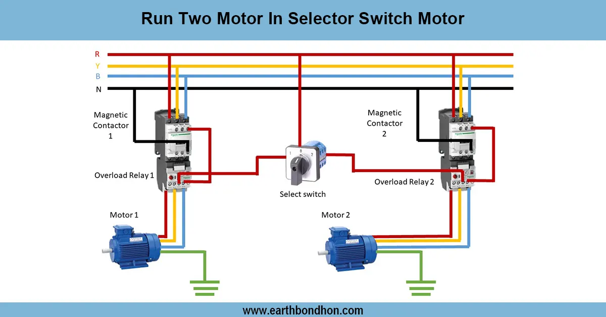
Run two Motors in Selector Switch
Learn how to connect an on-off delay timer with a contactor to control motors or loads with delayed ON and OFF functions safely and efficiently.

delayed switching contactor circuit
Connection On-off delay timer with a contactor can be used to switch a motor or a load controlled manually with a fixed ON and OFF delay. It guards equipment and allows the sequential running of equipment automatically.
timer with contactor connection
Contactor wiring On-off delay timer has a delay that is set and switches a load or a motor ON or OFF. The timer coil input is connected to the AC supply, and it operates the contactor coil. The timer output contacts activate the contactor, and this activates the motor or load. Depending on the type of timer, this arrangement may include an ON-delay option and an OFF-delay option. Safe operation is not possible without proper connections of the neutral and earth. This wiring eliminates unexpected motor acceleration or deceleration, decreases mechanical stress, and, with industrial automation, motor control, and lighting circuits, it operates in a sequence. Testing includes testing of the supply, the delayed reaction of the contactor and load, and testing of the correct functioning of both ON and OFF delays. Proper installation guarantees safe, stable, and effective work of the timer-controlled system of contactors.
Work & Installation (Input → Output Summary)
- ConnectAC supply to the timer coil input.
- Connecttimer output contacts to the contactor coil.
- Connect theload (motor or lamp) to the contactor output terminals.
- Set thedesired ON-delay and OFF-delay times on the timer.
- Ensure properneutral and earth connections.
- Apply supply; the timer controls contactor energization to switch the load with delays.
Testing & Final Adjustments
- Verify wiring: supply, timer coil, timer output, contactor coil, load, neutral, and earth.
- Apply supply and observe delayed activation of the contactor for ON-delay.
- Switch off the supply or simulate the control signal to verify the OFF-delay operation.
- Adjust timer settings to achieve desired delay durations.
- Inspect neutral and earth connections for safety.
- Perform multiple ON/OFF cycles to check repeatability.
- Verify contactor operation and load activation timing.
- Ensure timer rating matches the contactor coil and load voltage.
- Check for loose or exposed wires and mechanical issues.
- Document wiring and settings for future maintenance and troubleshooting.
Frequently Asked Questions - Run two Motors in Selector Switch:
What is an on-off delay timer?
A timer that controls load activation and deactivation after preset delays.
Where is it used?
For motors, lighting, and automation systems needing delayed switching.
How does it work with a contactor?
Timer output energizes the contactor coil to switch the load after delay.
Can it control motor start and stop delays?
Yes, ON-delay and OFF-delay functions are possible.
Is earthing required?
Yes, for safety and proper operation.
Can multiple loads be controlled?
Yes, if the contactor rating matches the load current.
How to set delay times?
Adjust the timer's ON-delay and OFF-delay settings as required.
Does it prevent mechanical stress?
Yes, delayed switching reduces sudden starts and stops.
How to test the system?
Apply supply and observe contactor and load activation according to delays.
Is it suitable for industrial motors?
Yes, widely used in industrial motor control and automation systems.