MCCB Wiring Diagram
Learn MCCB simple diagram with wiring connections, input-output, protection features, and installation guide for safe electrical distribution.

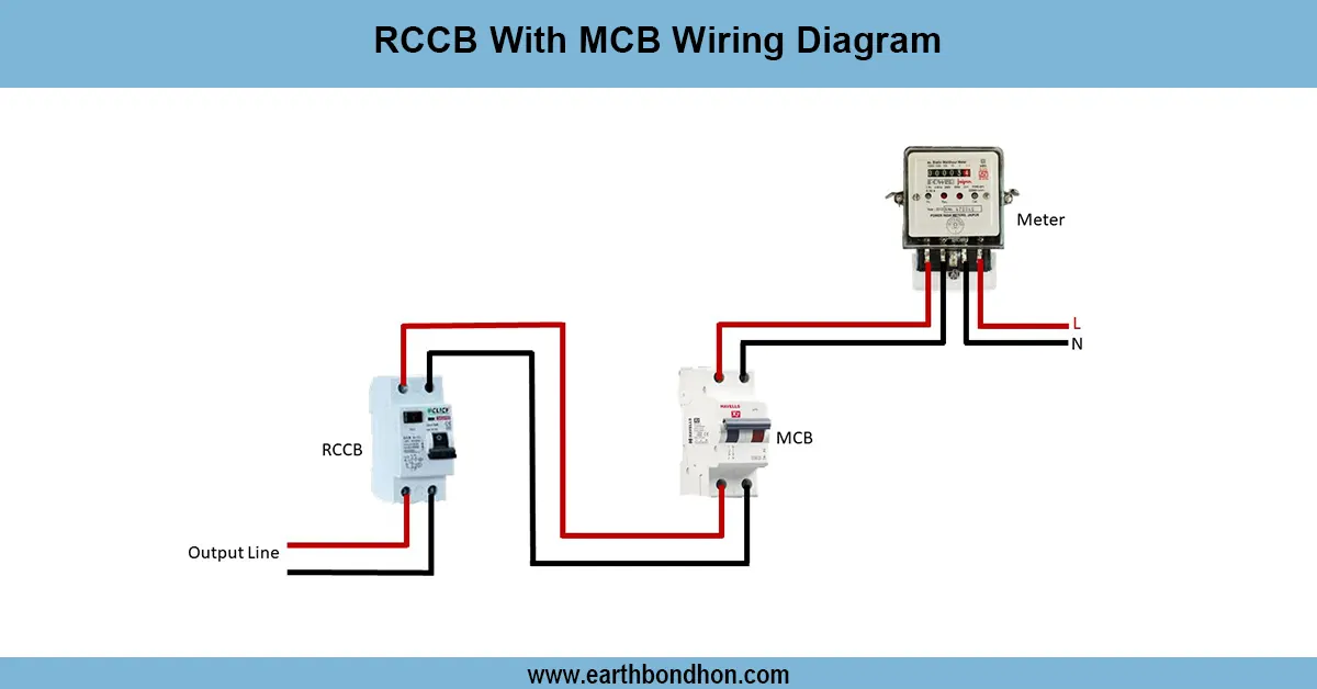
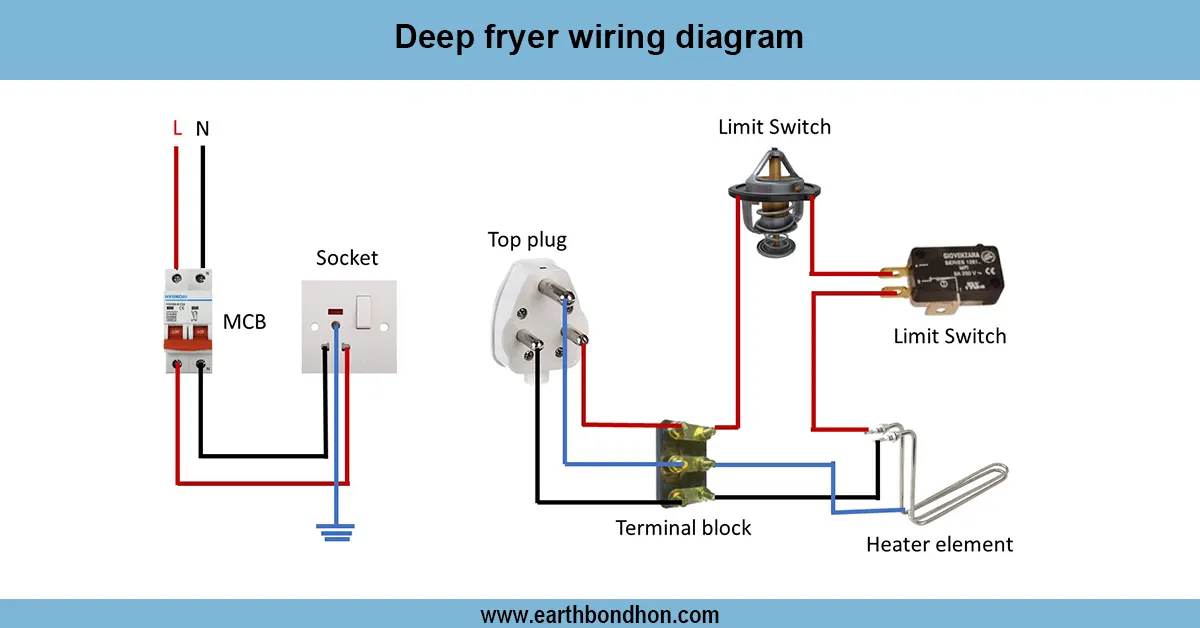
MCCB simple diagram
The MCCB simple diagram indicates input and output connections where the breaker is protecting the circuits against overload and short circuiting. It can regulate lighting, motors, etc.
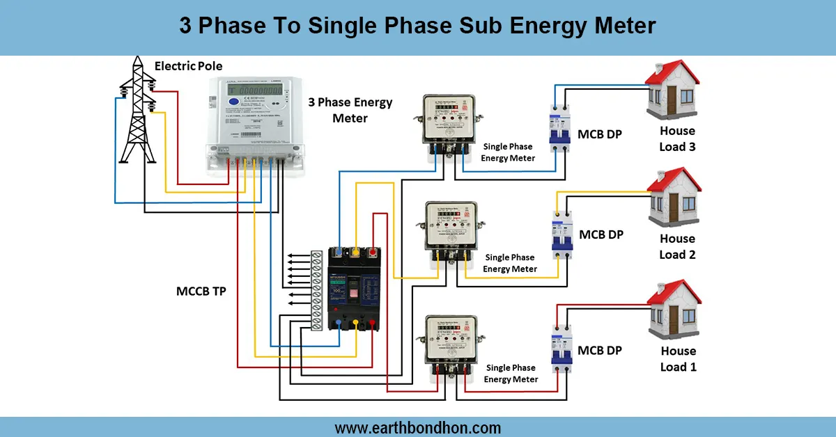
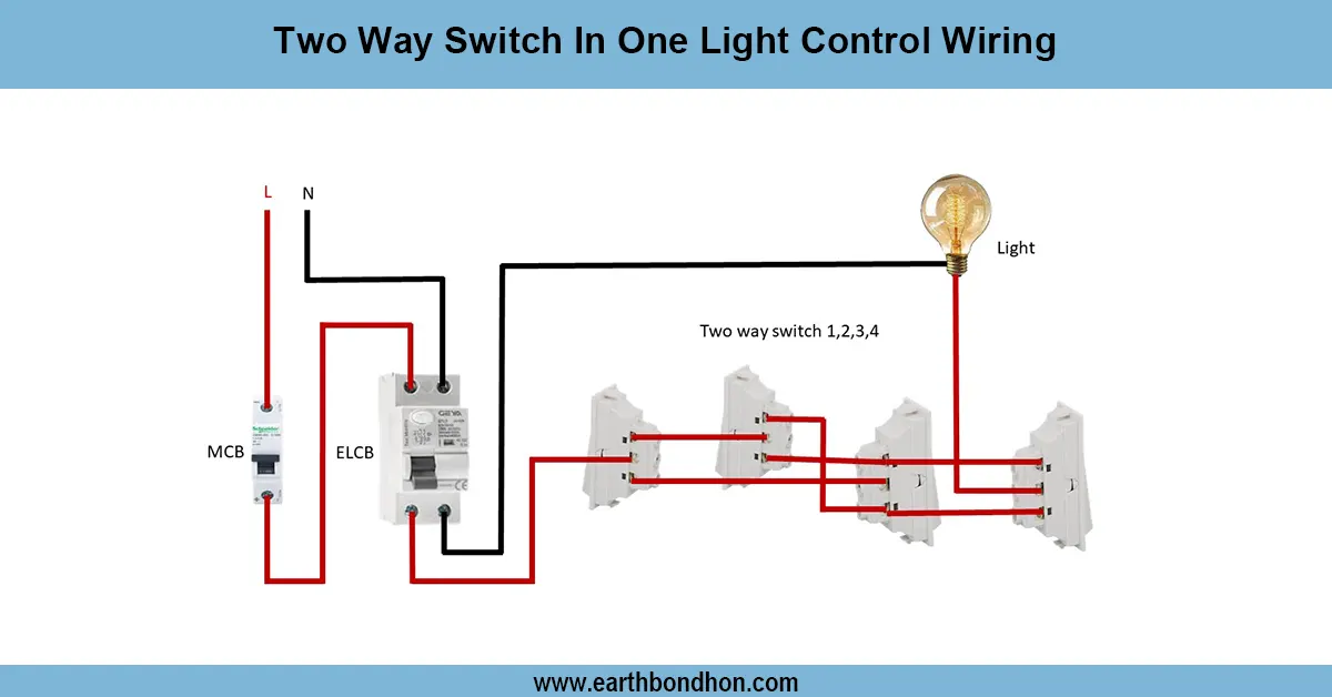
three phase MCCB connection
A simple diagram of an MCCB (Molded Case Circuit Breaker) illustrates how the power moves through the main supply and the breaker to other circuits. The MCCB ensures against overloading and short circuits. The schematic explains the input terminals that are attached to the incoming power line and the output terminals attached to the load. The breaker may be automated with control switches or contactors. Industrial, commercial, and very large residential installations utilise MCCB to offer trustworthy protection. The safe operation requires correct wiring, earthing, and current limiting to the required levels.
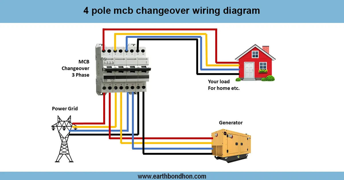
Work / Installation (Inputs → Outputs)
The input power supply is used to link to the MCCB input terminals (phase and neutral in a single or three-phase line). Output terminals supply downstream circuits, including motors, lighting, or panels. The MCCB automatically trips when there is an overcurrent to avoid appliance and wiring damage. To install, be sure that the breaker is of the correct size to carry the load and that it is correctly installed in a distribution board. Install input and output wires appropriately, insulate, and earth the MCCB frame properly to provide safety. Motor start/stop, or automation switches, push buttons, or control relays may be added. Adhere to electrical requirements and provide ventilation.
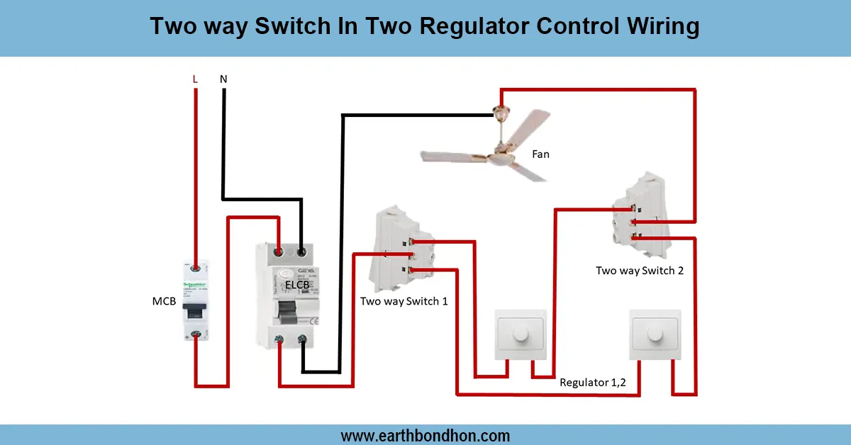
Testing & Final Adjustments
Once installed, ensure that the MCCB has been wired properly. Verification of continuity of checks between input and output terminals. Test the breaker to make sure that the breaker trips at the rated overload current. In the case of a three-phase MCCB, ensure the right phase sequence. ON/OFF operation and any control switches connected. Check wiring to ensure tightness, insulation, and earthing. Write on the MCCB the current it is rated at and its use (e.g., Motor, Lighting). Make sure that there are no wires in contact with the enclosure or terminals. Proper testing will provide safe and reliable performance and avoid damaging other equipment.
Frequently Asked Questions - MCCB Wiring Diagram:
What is an MCCB?
MCCB is a Molded Case Circuit Breaker that protects circuits from overload and short circuits.
Where is MCCB used?
In industrial, commercial, and large residential installations.
How does MCCB protect a circuit?
It trips automatically when the current exceeds rated limits.
What is the difference between MCB and MCCB?
MCCB can handle higher currents and is adjustable; MCB is for lower ratings.
Can MCCB control motors?
Yes, it can be used with motor starters or contactors for motor control.
How many terminals does MCCB have?
Single-phase has 2 terminals; three-phase has 3 or 4 terminals.
Is earthing required for MCCB?
Yes, to prevent electric shocks and ensure safety.
What is the input and output in MCCB diagram?
Input terminals receive power from supply; output terminals feed downstream loads.
Can MCCB be wired in series with MCB?
Yes, MCCB can protect multiple MCBs downstream.
How to test an MCCB?
Apply load, check manual ON/OFF, and verify tripping at rated current.