Tunnel Wiring Circuit Diagram
Learn the tunnel wiring circuit diagram, including lighting, emergency, ventilation, and safety systems, with proper protection and control connections.

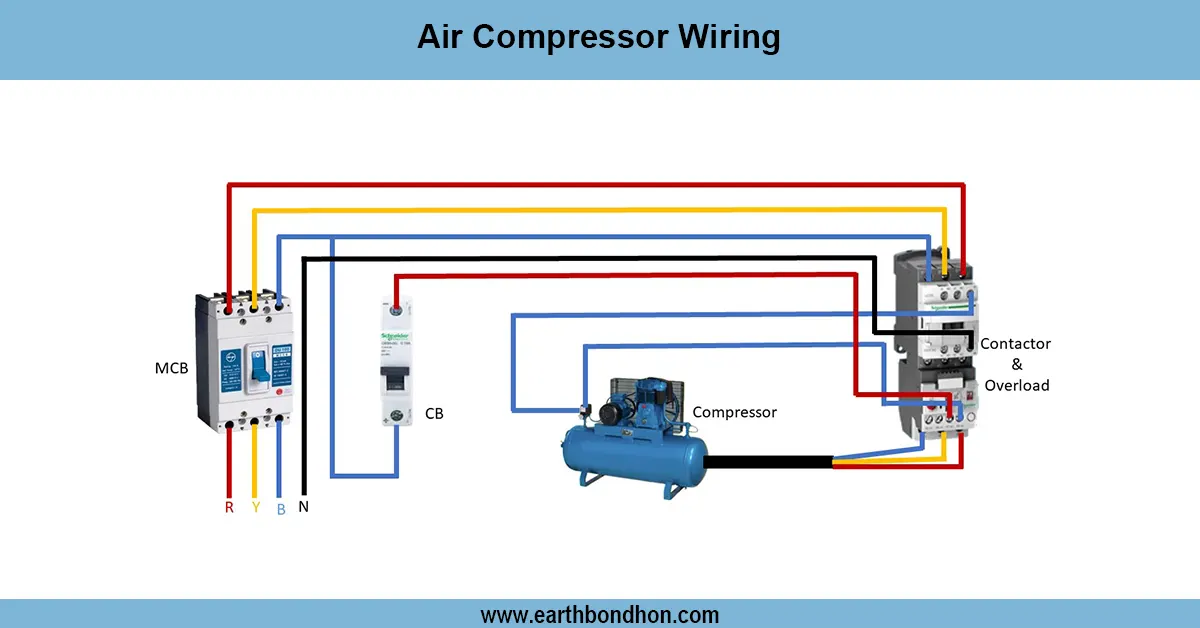
tunnel lighting circuit diagram
The circuit diagram of the tunnel wiring illustrates the method of installing safe wiring of lighting, ventilation, emergency, and control systems to maintain continuous running and safety of underground tunnels or road tunnels.
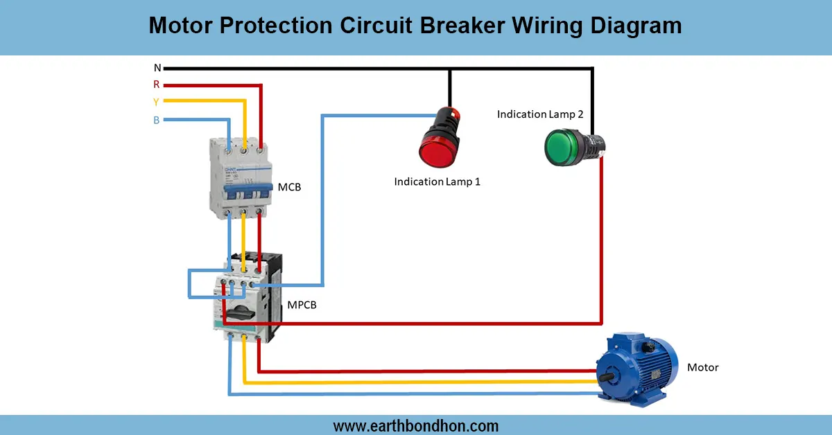
tunnel lighting control system diagram:
A tunnel wiring circuit diagram is a diagram of the electrical wiring of tunnel systems, such as lighting, ventilation fans, emergency lights, and safety alarms. The system is usually supplied with 3-phase power at heavy loads, such as fans and pumps, and single-phase lighting and control circuits. Wiring is a process of linking supply lines, protective devices (MCB, RCCB, fuses), contactors, timers, and relays to have an automatic operation. Backup power or UPS is used to link the emergency systems to ensure they are operational at the right time. The earthing and management of cables is important for safety and maintenance. This diagram will ensure that the lighting intensity, ventilation, and emergency systems are deployed effectively to ensure that there is a safe environment within tunnels. Adherence to the wiring diagram leads to efficient and easy installation, easy troubleshooting, and adherence to the electrical safety standards.
Work & Installation (Input → Output,)
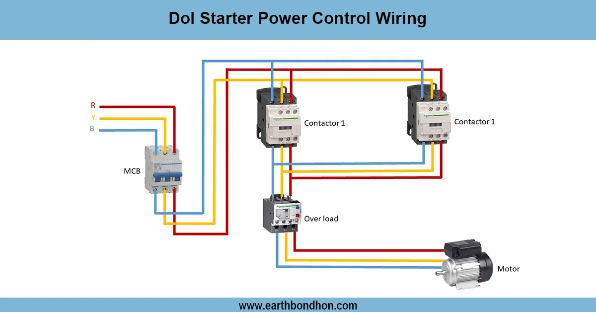
- Power Supply: Connect three-phase supply for fans and pumps; single-phase for lights and controls.
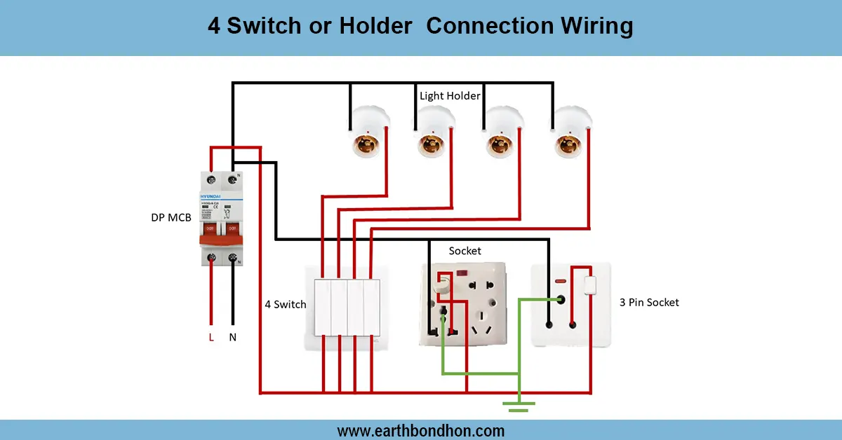
- Distribution Board: Feed supply through MCBs, RCCBs, and fuses for protection.
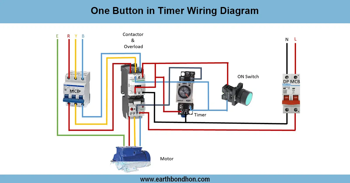
- Lighting Circuit: Connect tunnel lights through contactors or timers for automatic ON/OFF.
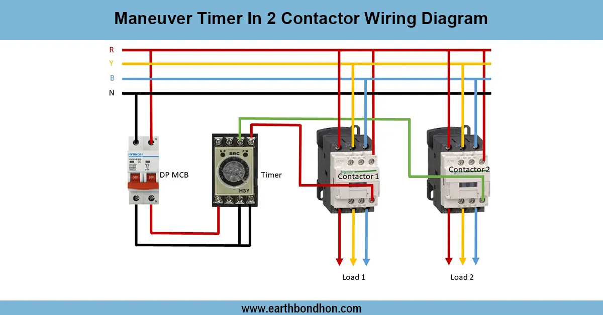
- Ventilation System: Wire ventilation fans using relays and timers to control airflow based on sensors.
- Emergency System: Connect emergency lights and alarms to backup UPS or generator supply.
- Control Devices: Use switches, PLC, or timers for automation of lighting and ventilation.
- Earthing & Cable Management: Proper earthing for all systems and neat cable routing to ensure safety.
- Testing: Check each circuit individually before commissioning.
Testing & Final Adjustments
Phase-by-phase energy the system after wiring. Check light circuits to ensure that they work on/off. Test ventilation fans are driven by timers or sensors. Test backup supply of check emergency lights and alarms. Check all connections to ensure they are tightened, insulated, and that earthing is done correctly. Measure voltages across circuits to make sure that there are no drops. Test protective devices (MCB/ RCCB) to make sure that they trip in faulty situations. Circuits and panels are labelled in a manner that is easy to maintain. Conduct various cycles of lighting and ventilation systems to ensure good functioning. Effective testing safety of tunnels, minimization of the threat of an electrical hazard, and the ability to maintain the work of life-saving systems in the event of a supply loss.
Frequently Asked Questions - Tunnel Wiring Circuit Diagram:
What is tunnel wiring?
Electrical wiring for lighting, ventilation, emergency, and control systems in tunnels.
What type of power supply is used?
Three-phase for heavy loads and single-phase for lighting and controls.
Are protective devices needed?
Yes, MCBs, RCCBs, and fuses for safety.
How is ventilation controlled?
Using timers, relays, or PLC based on sensors.
Are emergency systems connected?
Yes, to backup UPS or generator supply.
Is earthing necessary?
Yes, for all circuits for safety.
How to test tunnel wiring?
Phase by phase testing of lights, fans, and emergency systems.
Can PLC be used?
Yes, for automatic control and monitoring.
Why follow the wiring diagram?
Ensures safety, reliability, and compliance with standards.
What if a circuit fails?
Check protective devices, wiring connections, and load integrity.