

Relay To Control Lamps Wiring
Learn how to wire a relay to control lamps, including coil, NO/NC contacts, power supply, and safe connections for efficient lighting control.

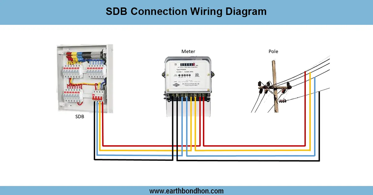
industrial lamp relay wiring
Lamps may be controlled by a relay operated by its coil through changing of NO/NC contacts. This enables switches or automation that have low current to safely handle high current lighting loads.
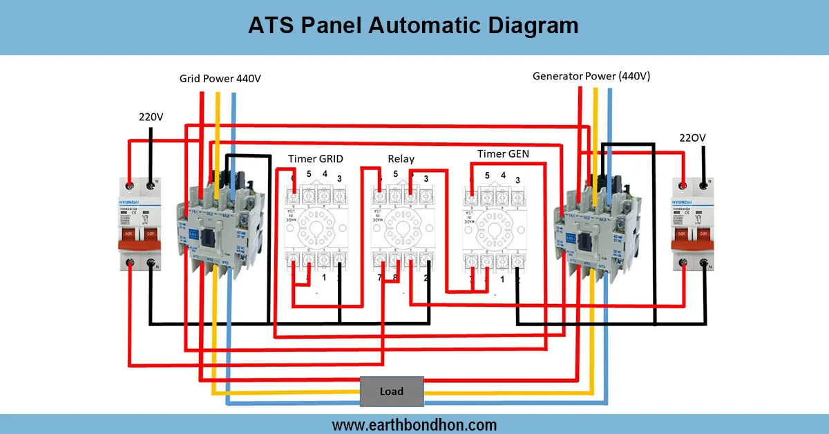
lighting relay connection
A lamp to control wiring diagram illustrates the way a relay can be employed to power on or off one or more lamps with a high degree of safety. The lamps are then connected to the relay coil, and a control switch/ automation device is connected to the normally open (NO) or normally closed (NC) contacts. As the coil is energized, the NO contacts are closed, which powers the lamps, and the NC contacts are open, depending on their use. Live, neutral, and earth connections should be proper and neutral and earth. The relay circuit and the lamps should be provided with fuses or MCBs to guard against overcurrent. Relays enable low-current control circuits to control high-current loads, such as lamps, without connecting the load directly to the control switch. The technique has found a common application in domestic automation, factory lighting, and street lighting. The testing is done to verify that the coils are energized, the contacts switch occur, and the lamps are lit. Proper installation ensures a long life of the relays, the lamp can be properly controlled, and it is safe for the operators.
Work & Installation (Input → Output Summary)
- Connectlive and neutral supply to the relay coil.
- Connect a control switch or automation device in series with the coil.
- ConnectNO contacts of the relay to the lamps and live supply.
- Connectneutral and earth to the lamps.
- Addfuse or MCB protection for safety.
- Test coil operation to ensure contacts switch correctly.
- Verify lamp illumination when relay is activated.
- Ensure secure mounting of the relay and proper insulation of wires.
Testing & Final Adjustments
- Verify wiring of coil, NO/NC contacts, and lamp connections.
- Check the control switch or automation device that energizes the relay coil.
- Observe lamps turning ON/OFF as the relay is activated.
- Measure coil voltage to ensure proper operation.
- Inspect for loose terminals and exposed wires.
- Confirm the fuse or MCB is rated for the load current.
- Test multiple switching cycles for reliability.
- Check NC contacts if used for alternative switching.
- Ensure proper earthing for safety.
- Document wiring diagram and control setup for maintenance.