Voltmeter Selector switch wiring diagram
Learn how to connect a 3-phase voltmeter using a selector switch for measuring RY, YB, and BR line voltages in electrical panels.

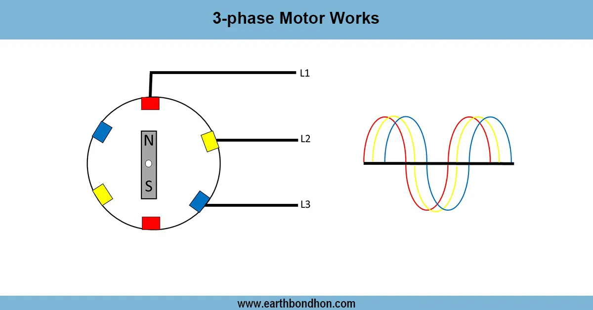
3 phase voltmeter wiring diagram
To attach a 3-phase voltmeter to a selector switch, wire the voltmeter between the terminals of the switch to the 3-phase supply lines. Apply RY, YB, and BR voltages by rotating the switch.
how to connect voltmeter selector switch
To measure voltages between phases (RY, YB, BR) at line-to-line voltages, a common use of a 3-phase voltmeter with a selector switch connection is in an electrical distribution panel. This is done by using a 3-position selector switch to connect a single voltmeter that is. To measure each of the three line voltages, one has to switch the voltmeter positions.
The wiring has a voltmeter, a switch, and an incoming 3-phase supply. The selector switch is connected in a different way that will allow the voltmeter to read R-Y, Y-B, and B-R voltages separately. This construction is space-efficient, economical, and easier to monitor residential, commercial, and industrial panels.
Through this connection, electricians and engineers are able to swiftly check and keep track of the balance of voltages throughout phases and the smooth functioning of 3-phase loads such as motors, pumps, and machinery.
Work / Installation (Inputs → Outputs)
The installation commences with 3 3-phase supply lines (R, Y, B). The selector switch contains several input terminals for every phase line. The voltmeter is linked to the common output terminals of the selector.
Rotation of the selector knob connects the voltmeter to two phases (R-Y, Y-B, B-R). In this way, the voltmeter shows the line voltage. Before wiring, proper MCB protection should be undertaken to ensure safety.
This process enables only one voltmeter to read all three phase voltages, which saves panel cost and space.
Testing & Final Adjustments
When wired, energize the supply and switch the selector switch to each position. The voltmeter must show the respective line voltage (R-Y, Y-B, B-R). In case the reading is zero or unstable, then check the wiring of the selector and ensure that there is proper phase connection.
Make sure the voltmeter value is equal to the supply voltage (e.g., 0-500 V on 415 V systems). Ensure that wiring is secure and well-insulated in order to avoid sparks or overheating.
Properly adjusted, this arrangement gives stable 3-phase voltages on a single voltmeter and includes a selection switch.
Frequently Asked Questions - Voltmeter Selector switch wiring diagram:
What is a 3-phase voltmeter with selector switch?
It is a setup to measure RY, YB, and BR voltages using one voltmeter.
Why use a selector switch with voltmeter?
It saves cost and space by using one voltmeter for all three line voltages.
How many positions does the selector switch have?
Generally three positions for RY, YB, and BR measurement.
Can this be used in single-phase systems?
No, it is designed for 3-phase monitoring.
What voltage range is used for 3-phase systems?
Typically 0–500V range for 415V 3-phase supply.
Is MCB protection necessary?
Yes, always use MCB before connecting to prevent damage.
Can digital voltmeters be used with selector switches?
Yes, both analog and digital voltmeters can be used.
Where is this setup commonly used?
In distribution panels, control panels, and motor starter boards.
Does the selector switch need maintenance?
Occasional cleaning and tightening ensures smooth operation.
Can neutral be used in this connection?
No, only line-to-line voltages are measured without neutral.