Shunt Trip Breaker Wiring Diagram
Learn how to wire a shunt trip breaker, including control circuits, trip coil connection, safety interlocks, and proper protection for industrial or home systems.

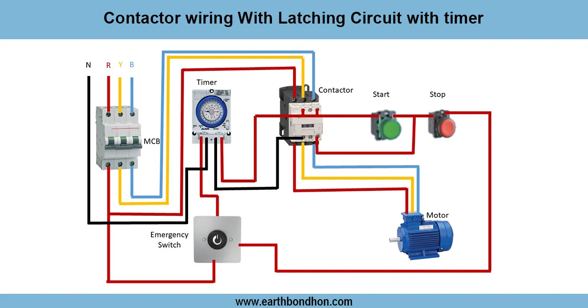
breaker control wiring diagram
A remote tripping can be carried out using a shunt trip breaker. Trip coil, fuses, and interlocks should be wired properly to provide safe and reliable with industrial or home applications.
MCB/ACB shunt trip connection
In a shunt trip breaker, a circuit breaker can be tripped remotely by applying an outside signal to it. The breaker is fitted with a trip coil that, on energization, opens the contacts immediately. Wiring is done to make the control voltage (AC or DC) contact the trip coil through a push button, relay, or interlock circuit. The terminals in the main breaker are the normal load, and the shunt trip wiring is a guarantee of remote or emergency disconnection. The precautions that can be taken are to use fuses or MCBs in the control circuit, to label control voltage in AC/DC properly, and to avoid cross connections. Shunt trip breakers are mostly applied in the industrial automation system, emergency shutdown system, and safety interlocks. Testing requires the control circuit activation and ensuring that the breaker does not require a long time to trip without causing a reaction of the main supply. Allows safe and reliable,e and fast disconnection in case of an emergency or during automation work due to the proper installation.
Work & Installation Summary
- Identify themain breaker and its shunt trip coil terminals.
- Connect thecontrol voltage (AC/DC) to the shunt trip coil.
- Installfuses or MCBs in the control circuit for protection.
- Integrate push buttons, relays, or interlocks for remote or emergency operation.
- Label AC/DC control voltage clearly to avoid mistakes.
- Mount breaker and control devices securely.
- Route control wiring with properinsulation and separation from load lines.
- Test the control circuit by activating the push button or relay.
- Verify that the breaker trips immediately without affecting other circuits.
- Document wiring diagram and operational instructions for maintenance.
Testing & Final Adjustments
- Checkincoming load wiring and trip coil terminals.
- Verifycontrol voltage continuity through fuses or MCBs.
- Testpush button or relay activation for proper tripping.
- Ensure breaker trips instantly without delay.
- Inspect wiring fortight connections and proper insulation.
- Confirm no interference with normal breaker operation.
- Label all control and load terminals for clarity.
- Repeat test multiple times to ensurereliable operation.
- Ensure AC/DC voltage levels match trip coil rating.
- Document the wiring and test results for reference.
Frequently Asked Questions - Shunt Trip Breaker Wiring Diagram:
What is a shunt trip breaker?
A breaker that can be tripped remotely via an external control signal.
How does it work?
When the trip coil is energized, it opens the breaker contacts immediately.
Is protection needed in the control circuit?
Yes, fuses or MCBs protect the control wiring.
Can it be used for AC and DC?
Yes, ensure the control voltage matches the trip coil rating.
Where is it commonly used?
Industrial automation, emergency shutdown systems, and safety interlocks.
Can I test it safely?
Yes, energize the control circuit and verify breaker trips without affecting other circuits.
What devices can control the trip coil?
Push buttons, relays, or interlock circuits.
Is labeling important?
Yes, clearly label AC/DC control and load terminals for safety.
Does it affect normal operation?
No, the shunt trip circuit is separate from the main load path.
Can multiple breakers have shunt trip?
Yes, each breaker requires its own control wiring and protection.