3-phase Motor contactor wiring diagram
Comprehensive 3-phase motor wiring guide showing correct connection of motor terminals, power supply, and starters for safe and efficient motor operation.

three phase motor starter wiring
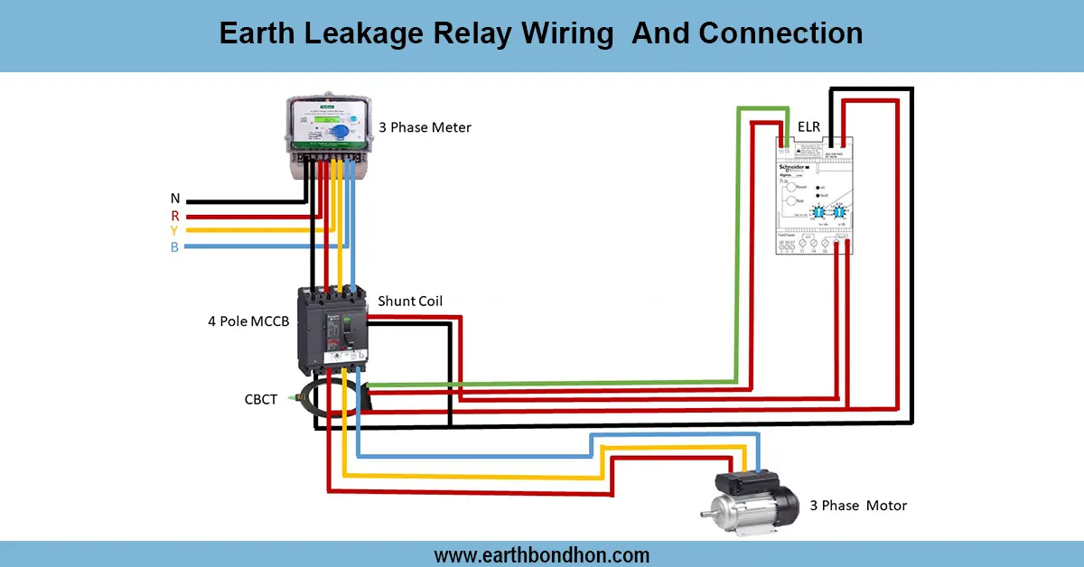
3 phase motor wiring consists of at least 3 power phases to the motor terminals in a star or a delta with a correct phase sequence and protective devices in order to operate reliably.
3-Phase Motor Wiring Summary & Key Points:
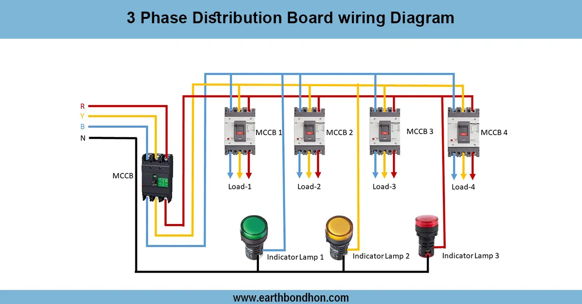
Power Supply: Three phase lines L1, L2, L3
Connection Types: Star (Y) for high voltage, Delta (Δ) for low voltage operation
Phase Sequence: Correct sequence ensures proper rotation
Reversing Rotation: Swap any two phases
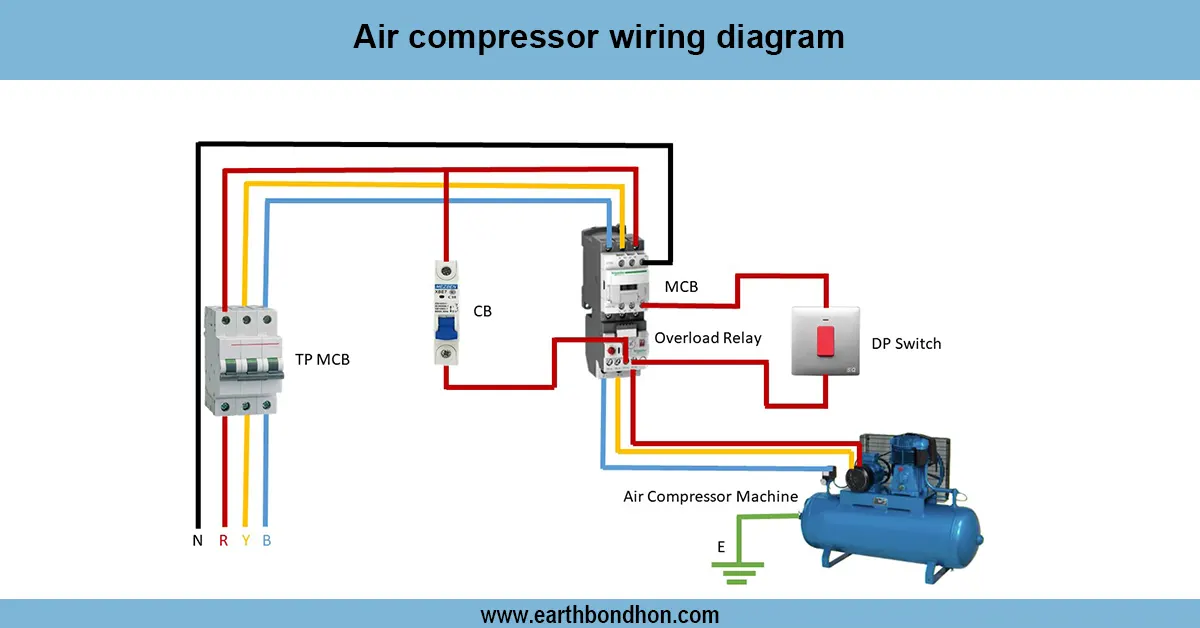
Protection: Use starters, overload relays, and breakers
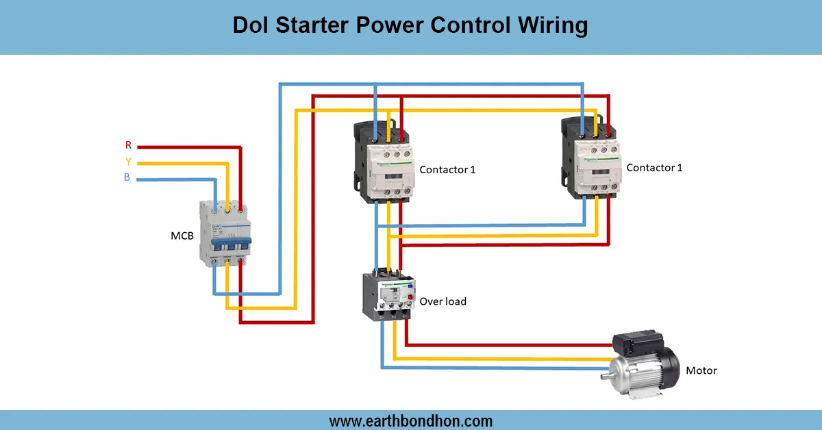
3 phase motor control wiring
Wiring of a 3-phase motor means wiring the motor with the motor leads correctly to the three power-supply lines (line 1, line 2, and line 3) to provide safe and efficient operation. The motors may be star (Y) connected or delta ( 3 ) connected, based on the voltage involved and applications needs. The override elements necessary to control motor operation as well as to protect against faults are the motor starter and protective devices such as overload relays and circuit breakers. Sufficient wiring entails the terminals of the motor to be connected to the supply of power that shares the right phase sequence in such a way that the motor goes in the preferred direction. A flip-flop of the two phases reverses direction of rotation of the motor. This termination manual deals with the identification of terminals, wiring practices, wiring of starter, and the requirements and practices involved in installing industrial and commercial motors safely.
3 phase motor installation
| Component | Connection | Purpose |
|---|---|---|
| L1, L2, L3 | Connected to motor terminals U, V, W | Provide 3 phase power to motor |
| Star Connection | Connect motor terminals together at a neutral point | Used for high voltage start |
| Delta Connection | Connect terminals in a triangle loop | Used for low voltage operation |
| Overload Relay | Connected in series with motor supply | Protects motor from overheating |
| Starter Coil | Controls motor start/stop operation | Energizes motor supply contactors |
Frequently Asked Questions - 3-phase Motor contactor wiring diagram:
What is 3 phase motor wiring?
Connecting three power phases to motor terminals for operation.
What are star and delta connections?
Methods of connecting motor windings for voltage compatibility.
How to reverse motor rotation?
Swap any two of the three phase supply lines.
What protective devices are used?
Overload relays, circuit breakers, and starters.
Why is phase sequence important?
It determines motor rotation direction.
Can a 3 phase motor run on single phase?
Yes, with additional equipment like capacitors or converters.
What is a motor starter?
A device to safely start and stop the motor.
How to identify motor terminals?
Usually marked U, V, W on the motor nameplate or terminal box.
Is wiring different for different motor sizes?
Basic principles are same; protective device ratings vary.
Who should wire a 3 phase motor?
Qualified electricians to ensure safety and compliance.