Dol Starter Control Circuit Wiring Diagram
Learn Direct-On-Line (DOL) starter motor wiring with phase voltage indicators for safe operation, overload protection, and correct three-phase motor control.

motor starter with voltage indicators
Phase voltage indicators on DOL starter wiring permit a three-phase motor to be connected to the supply directly, and the phase voltages are indicated in real time. It provides proper phase-alignment, operator safety ,and overload in industrial use.
DOL starter motor wiring diagram
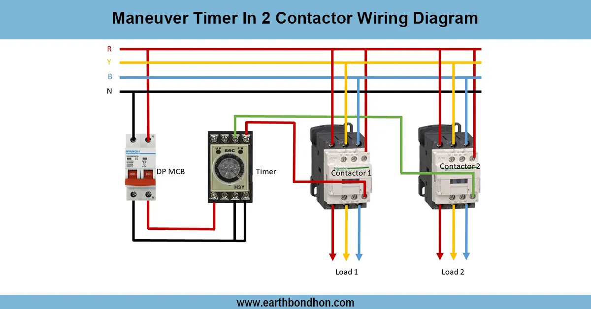
Direct-On-Line (DOL) starter motor wiring incorporates phase voltage indicators and operates a three-phase motor directly off the supply as voltages of the supply are monitored. The system has a contactor, an overload relay, a start/stop push button, and a 33-phase indicator lamp. On pressing the start button, the contactor becomes energized, and the motor is connected directly to the three-phase supply. It has indicator lamps that are connected across every phase, indicating that there is a voltage supplylyp,y, and the operators can verify that the correct phase supply is available before the start of the motor. The overload relay is used to guard against overcurrent the The stop button will de-energize the contactor and switch off the motor. This arrangement provides safe and dependable motor performance, phase control, short circuiting defense, and the security of employees. Testing includes checking of phase indicators, motor starting/stopping, and correct overload operation. This is a common wiring in industrial motors, pumps, fans, and manufacturing machines.
Work & Installation (Input → Output Summary)
- Incoming Three-Phase Supply passes through the DOL starter contactor.
- Start Push Button energizes the contactor coil, connecting motor to supply.
- Stop Push Button disconnects the contactor, stopping the motor.
- Overload Relay trips in case of overcurrent, protecting the motor.
- Phase Voltage Indicators (lamps) are connected across each phase to monitor the presence of supply.
- Motor Output runs at full line voltage safely and reliably.
Testing & Final Adjustments
- Check all connections: line, contactor, push buttons, overload, indicators, and motor.
- Turn ON supply; phase indicator lamps should glow for all three phases.
- Press start; motor should run smoothly, and indicators remain ON.
- Press stop; motor should stop immediately.
- Simulate overload; overload relay should trip and disconnect the supply.
- Confirm proper phase sequence; motor rotates correctly.
- Inspect terminals for secure connections and insulation.
- Test repeated start/stop cycles for reliability.
- Ensure indicator lamps function under load conditions.
- Record operational parameters and testing results for maintenance.