3 Phase Forward Reverse Motor Control
Learn how to wire a 3-phase forward-reverse motor control circuit with contactors, push buttons, and protection for safe and efficient motor operation.

3-phase motor control wiring diagram:
A 3-phase forward-reverse motor control circuit is a circuit of wiring that allows an electric motor to be operated in Either direction. It operates contactors, interlocks, and push buttons to operate the motor safely without destroying it. the system.
3-phase motor starter wiring:
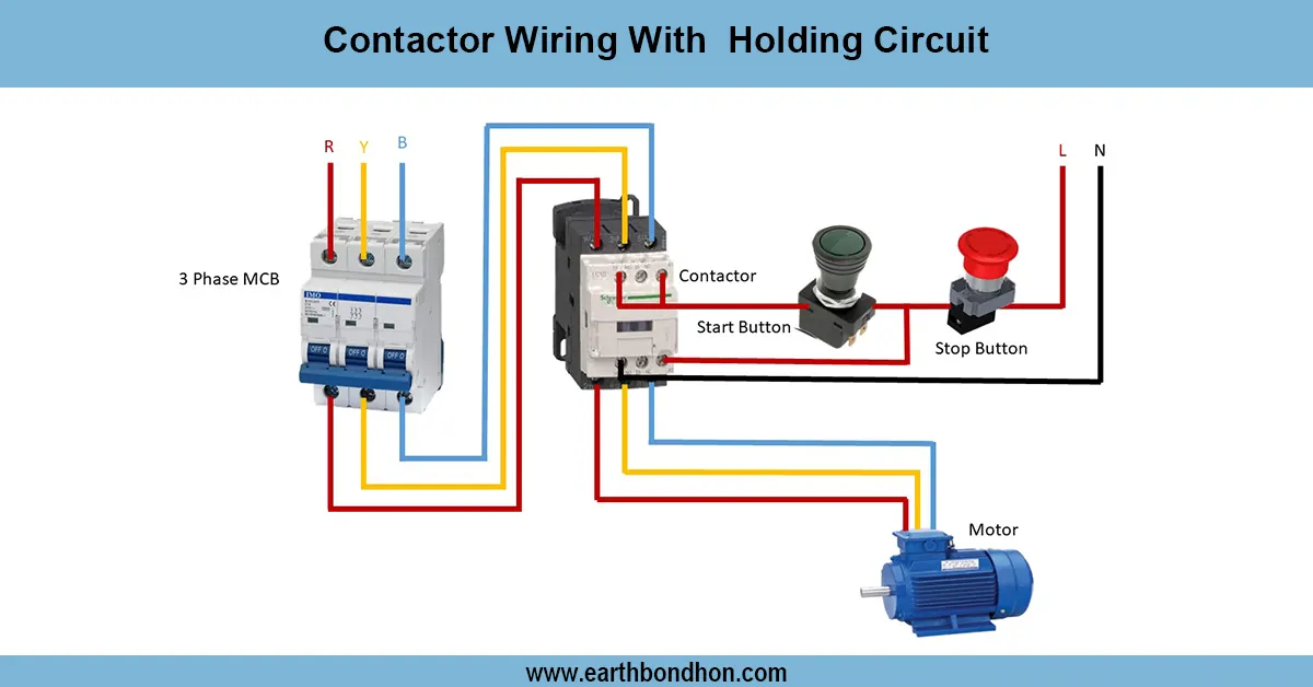
Contactors, push buttons, and interlocking enable a 3-phase forward-reverse motor control circuit to permit an induction motor to operate in a forward or reverse mode. This construction is widely applied to industries in conveyor belts, cranes, lifts, and others that have a need to be rotated in both directions. Two contactors are usually used in the circuit, one forward and one reverse contactor, which are interlocked so that they cannot operate simultaneously. The direction of the motor is controlled by push buttons or switches, and overload relays are used to offer protection against faults. The wiring is made in specific ways to have safe and reliable operations, thus a very important way of control in automating motor systems. Proper installation and testing will play a key role in avoiding the risks and satisfactory reversing of the motor.
⚡ Work & Installation (Input → Output):
The input supply, in this circuit, is a 3-phase AC supply, which is connected with two contactors (one forward and the other reverse). Any two contactors are interlaced with an interlock system to prevent short-circuiting in case the two are pressed. The push button station has buttons for Forward, Reverse, and Stop in order to be operated manually. The forward button is pressed, and the forward contactor is energized, and the motor starts moving forward. Turblescape Tube Fraudulent Financial Statements Fraudulent financial statements are created and made up by organized criminals targeting swindlers.<|human|>Pressing the reverse button reverses the connection, and the motor will rotate the opposite way. The number of contacts is connected in series with the contactors to add protection to the motor against surplus current. The eventual product is a motor that can operate in a safe manner both in forward and reverse.
Testing & Final Adjustments:
Once installed, ensure that you check all the wiring connections with the diagram. Check to ensure that the interlocking system is functioning to ensure that both contactors do not energize at the same time. Begin by pushing the forward button - make sure that the motor is in the proper direction. Next is pressing the stop and then the reverse button to ensure that the reversal is appropriately done. Check the current that the motor takes at load to make sure it is not excessive. Test the overload relay to ensure that it is working properly when overcurrent is present. In case of the wrong direction of motor current, switch any two phases. Wear proper safety equipment, and ensure that the motor is grounded. After a round of testing and modifications, the system will be stable enough to operate in the industry in the long term.