3 Phase Motor Star Connection Diagram
Understand the 3-phase motor star connection wiring for motor starting and operation, including wiring steps and benefits of star configuration.

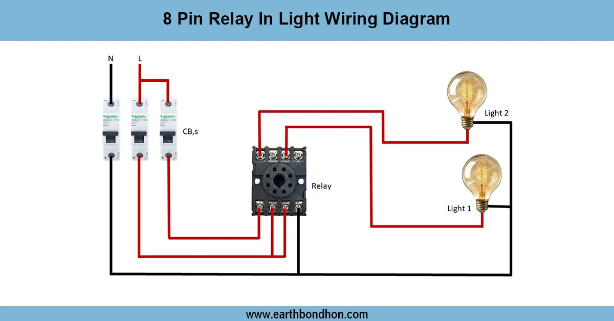
star connection wiring diagram
In a 3-phase motor star connection, all 3 windings go to a neutral point and free ends go to the supply phases. This minimizes starting current by putting less voltage on each winding so that the start is soft. Large motors require Star connection in order to start.
3 Phase Motor Star Connection Formula & Summary:
Line Voltage (VL): Voltage between any two supply phases
Phase Voltage (Vph):Vph = VL / √3
Starting Current: Reduced to 1/√3 of delta connection
Connection: Windings connected at one point (neutral), forming star (Y)
motor starting star connection
The 3-phase motor star connection is a usual wiring practice where the three windings on the motor have a common shared neutral point, and this pattern takes the shape of a Y. This arrangement, applied mostly through the starting of the motor, limits the starting current and helps in getting smooth operation. In a star connection, each winding receives line voltage at a lower voltage (line voltage/ sqrt 3 ), and this limits the starting surge current. The motor can be switched to a delta connection and is able to run normally at full voltage then. Star connection is desirable as it helps to minimize mechanical strain and electrical demand when starting a motor. The wiring should have the connection of the end of the three windings terminated between each other to make the neutral and the three phases provided to the ends of the other three windings. The configuration is fairly common with industrial motors to enhance efficiency and a longer lifespan.
star wiring motor diagram
Terminal | Connection | Description |
---|---|---|
U1, V1, W1 | Connected to supply phases L1, L2, L3 | Motor phase inputs |
U2, V2, W2 | Connected together to form a neutral point | Common star point |
Frequently Asked Questions - 3 Phase Motor Star Connection Diagram:
What is star connection in a 3 phase motor?
It connects all three windings at a common neutral point, forming a Y shape.
Why use star connection for motor starting?
To reduce starting current and mechanical stress on the motor.
How is phase voltage related to line voltage in star?
Phase voltage equals line voltage divided by square root of 3.
Can star connection be used for normal running?
Typically, motors switch to delta for normal running after starting.
What terminals form the neutral in star connection?
The ends U2, V2, and W2 of motor windings are connected together.
Does star connection reduce power output?
No, it reduces starting current but power output remains the same at running.
Is star connection safe for all motors?
It is commonly used for large motors requiring reduced start current.
How to identify star connected motor terminals?
Look for U2, V2, W2 connected together inside the motor terminal box.
What happens if star connection is wired incorrectly?
Motor may fail to start or run inefficiently, risking damage.
Is star connection suitable for single phase motors?
No, it is specific to three-phase motors only.
Related Posts

Air Compressor Wiring Circuit Diagram
Learn complete air compressor wiring with motor starter, pressure switch, overload relay, and automatic on-off control for safe and efficient operation.

Voltage Protection Device Wiring Diagram
Learn complete electrical protection using voltage protection devices for over-voltage, under-voltage, and short-circuit safety in residential and industrial systems.

Water pump control from two places
Step-by-step wiring diagram for controlling a water pump from two different locations using two-way switches, ensuring convenience and safety.

Pir-Motion Sensor wiring diagram
Learn how to wire a motion sensor in a security light with a clear diagram, step-by-step installation, working principle, and testing guide for safe setup.

2-way Switch Control in 3-Phase Motor
Learn how to use a 2-way switch control for a 3-phase motor to operate it from two locations, including wiring diagrams and safety tips for reliable control.

4 Gang Switch 4 Bulb Wiring
Learn how to wire a 4-gang switch to control 4 individual bulbs. Ideal for multi-light room setups with simple step-by-step wiring guide and diagram.