8-pin relay with Timer Wiring
Learn how to connect in assembly using 2 relay wiring with a diagram, step-by-step installation, and a safe switching method for home and industrial circuits.

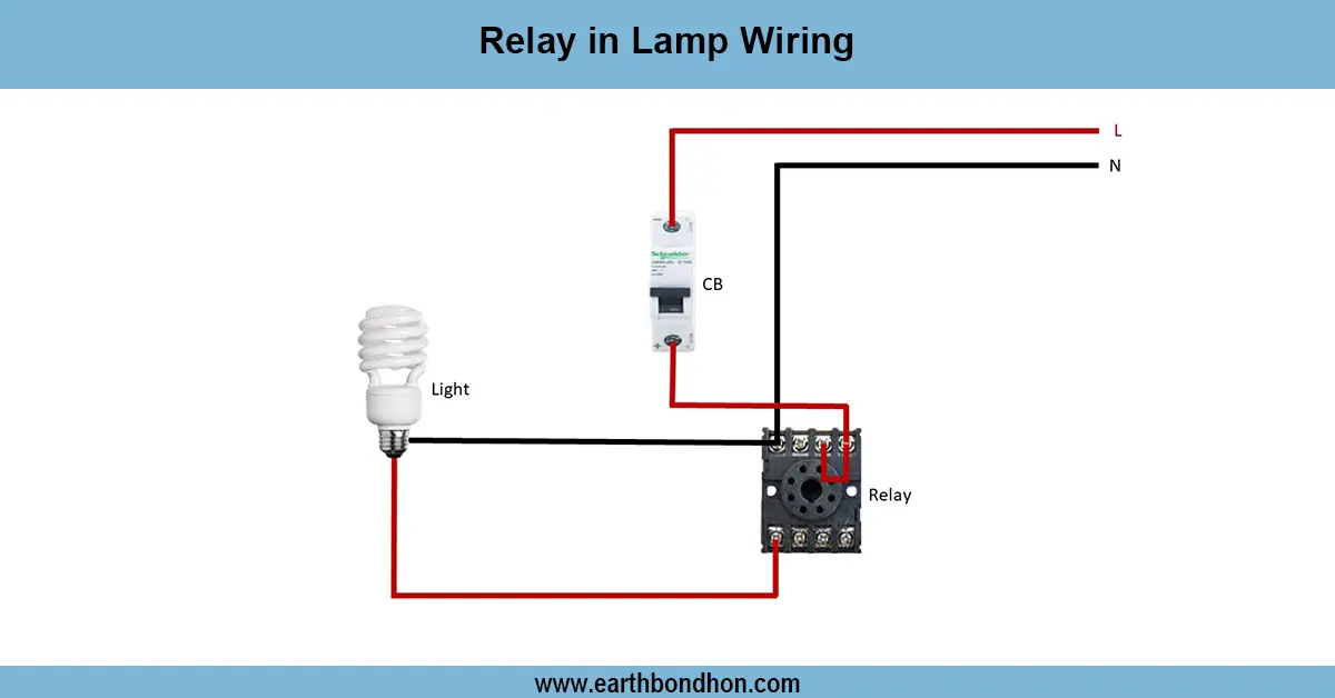
Relay switch connection
Electrical loads are usually controlled using a 2-relay wiring connection in order to have safety and efficiency. Relays are electromagnetic switches in which a low-powered circuit can manage a high-powered load. When two relays are assembled, different uses can be designed into the wiring, including forward/reverse motor control, interlocking, or dual load switching. All relays have in them a coil, common (COM), normally open (NO), and normally closed (NC) contacts. The circuit provides appropriate switching, protection, and automation by wiring the relays in the appropriate way. This technique finds extensive use in domestic appliances, automotive circuits, and the industry.
Relay assembly diagram
In electrical systems and electronics, a 2-relay wiring assembly is a convenient technique where two relays are used to switch loads, switching processes, or automation. Relays are electromagnetic switches that enable a signal of low power to operate high-power devices safely without direct connection. Relays have common (COM), normally open (NO), and normally closed (NC) contacts that can be hardwired differently depending on the one chosen.
They can be used in a variety of operations when interconnected in two-relay assemblies, including dual load switching, motor forward-reverse control, interlocking safety systems, or sequential switching. As an example, a relay that operates a forward motor can be used, where the other operates as a reverse motor, and a relay can be used to ensure the motor is operated safely. Correct installation consists of attaching the coil to a control supply and connecting the output load to a load terminal, usually through COM, NO, or NC.
The application of this wiring method is common in domestic appliances, industrial control, and automobile circuits, as well as water pumps. Correctly protected (including fuses or MCBs) and carefully tested, a 2 relay circuit is both safe and reliable in providing efficient load capacity.
Work / Installation (Inputs → Outputs)
The control switch or automation signal then switches the relay coils through the input supply in a 2-relay wiring assembly. There are terminals on each relay, namely, COM, NO, and NC. With the load across the relay output terminals, safe switching is possible without loads directly touched by the control switch. When the relay coil is energized, the COM terminal switches to NO, and current flows to the load connected. With two relays in series, more complicated operations can be performed, including dual load control, phase shifting, or forward-reverse operation of the motor. Anti-overloading in the form of protective devices such as fuses or MCBs ought to be added. Earthing and insulation should be done properly for safety. The technique minimizes the wiring complexity and provides a means of efficient and reliable load control.
Testing & Final Adjustments
Once the 2 relay assembly has been wired, verify the coil voltage rating (e.g.,12 V, 24 V, or 230 V AC) and make sure that the supply is as well. Turn on the circuit and push the control switch by hand to energize a relay. Measure continuity at the COM, NO, and NC terminals with a multimeter. Test it- Determine whether the load energizes and switches properly on each relay. As with a motor forward/reverse system, make sure to test them each way to ensure proper interlocking. Ensure that there is no loose wiring, overheating, or buzzing of the relay. Labeling of terminals and relay functions is good to aid in future maintenance. After this check, seal the assembly to the secure enclosure to avoid accidental contact. The last adjustments make the operation of the relays safe, smooth, and reliable in any electrical system.