Series Testing Board Wiring
Learn how to wire a series testing board to safely check appliances, identify faults, and test current flow without damaging electrical equipment.

how to make a series tester board
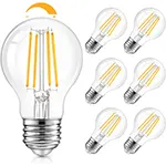
A testing board is an inexpensive and safe alternative to test electric appliances of sorts. It uses a light bulb to limit current supply in series with it so that people could identify the fault using the same without damaging the appliance. In case there is an overcurrent in an appliance, the bulb lights up and shows a visual fault indicator. This renders it very suitable to use in do-it-yourself diagnostics and electrical repair work carried out by the novice. Testing fans, motors, or chargers, a series board is a tool you can not do without as an electrician.
Series Test Formula Summary:
Ohm’s Law: V = I × R
The bulb controls current flow, and its brightness indicates the load's condition:
- Bright bulb: short circuit or high current draw
- Dim bulb: low current or normal operation
- Off bulb: open circuit or no load
series bulb tester circuit
A series testing board is a vital constructional electrical device providing the testing of the components and appliances in a safe manner. It is used to maintain the current through a test bulb in series with the load, hence protecting the device under test. In case of a short circuit in the appliance, the bulb glows brightly, which means there is a fault. The use of this simple but efficient tool will prevent any incidental scrap when performing the diagnostics. It is a simple-to-use device used regularly by electricians and hobbyists and contains the fundamentals of a socket, holder, bulb, switch, and wiring. A homemade tester board can save a lot of money and is safer both in a workshop and at home.
Series connection tester board
Appliance | Bulb Status | Indication |
---|---|---|
Fan | Dim | Normal Operation |
Shorted Iron | Bright | Short Circuit |
Mobile Charger | Off | Open Circuit |
Frequently Asked Questions - Series Testing Board Wiring:
What is a series testing board?
A device used to test electrical appliances by limiting current using a series-connected bulb.
How does a bulb in a tester board work?
The bulb lights up based on current draw, indicating the appliance’s condition.
What happens if the bulb glows brightly?
It indicates a short circuit or high current in the appliance.
Can I use LED bulbs in series testing boards?
No, use incandescent bulbs to handle varying current loads properly.
Is it safe for beginners?
Yes, it adds a safety layer when testing unknown appliances.
What components are needed?
Bulb holder, test bulb, switch, socket, wire, and a wooden/plastic base.
Where can I use this tester?
To test fans, irons, chargers, motors, etc., in homes or workshops.
Does it replace a multimeter?
No, it's a basic safety tool, not a measurement device.
What voltage does it support?
Standard 220–240V household appliances.
Why is the bulb not glowing?
Check for open circuit, no load, or broken bulb.
Related Posts

3 Phase SPD Connection
Detailed 3 phase SPD connection diagram showing how to wire surge protection devices to safeguard electrical systems from transient overvoltages.

Motor with on delay Timer
Wiring diagram for controlling two motors with a single timer to automate motor operation in industrial, agricultural, or manufacturing applications.

Corridor Wiring Circuit Diagram
Learn how to wire a corridor lighting system using switches at both ends. Ideal for homes, offices, and hotels to control lights from multiple points.

Corridor Hallway Wiring
Learn how to wire corridor hallway lights using one-way or two-way switch systems. Ideal for staircases, passages, and commercial buildings.

Selector Switch in Voltmeter Wiring
Learn how to wire a voltmeter with a 2-position selector switch to measure voltage from two sources or points safely and accurately.

2 Way Light Switch wiring 4 Methode
A 2-way light switch wiring diagram helps control a single light from two different locations. Common in staircases, long hallways, or large rooms.