3-phase Motor to single-phase Wiring Diagram
Learn how to run a three-phase motor using a single-phase power supply with a wiring diagram, capacitor connection, DP switch/MCB protection, and safe operation.

electrical socket wiring
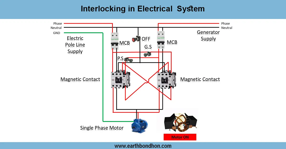
The following diagram illustrates a single-stage power supply in a three-phase motor, demonstrating how to combine the single-phase line, capacitor, and protection equipment to operate a three-phase motor safely and efficiently.
Formula & Table Summary:
A capacitor-start or capacitor-run motor can run a three-phase motor on a single-phase supply. Here, a capacitor is placed in series with the third terminal of the single-phase supply, and the two terminals of the supply are wired to two motor terminals to provide a phase shift. Isolation and protection are done through a DP switch or MCB. The technique is very popular in small-scale factories or domestic installations where a three-phase supply is not present. Correct wiring guarantees the smooth start of the motor, efficient operation, and elimination of overheating. The motor frame, capacitor, and switchboard are to be earthinged to ensure safety. According to the wiring diagram, there are clear connections of the single-phase supply to the motor terminals, the capacitor, the DP switch/MCB, and overload protection. With this system, it is possible to use a three-phase motor on a single-phase supply safely, with dependable starting torque, and efficient performance.
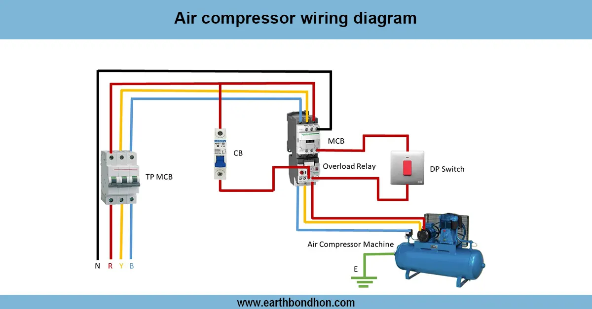
Work & Installation (Input → Output,)
- Input Supply: Single-phase 220V–240V AC supply.
- DP Switch / MCB: Provides isolation and protection against short circuits or overload.
- Capacitor: Connected in series with one of the motor terminals to create a phase shift for starting.
- Motor Terminals: Two terminals connected directly to supply; third terminal connected via capacitor.
- Earthing: Motor frame, capacitor, and switches grounded properly.
- Output: Motor starts and runs on single-phase supply; rotates in one direction efficiently.
This leads to small three-phase motors being used on occasions when there is only single-phase supply and so which means that the motor will not overheat, operate safely, and reliably.
Testing & Final Adjustments
Check connections after wiring and make sure that they are tight and well insulated. Turn on the DP switch/MCB and note the start of the motor. Check that the motor turns on without any problems, gains normal speed, and operates without undue vibrations and noises. Measure voltage on the motor terminals (~ 220 V -240 V) and make sure the capacitor is wired properly. Make sure that the motor does not overheat. Earthing connections are verified by confirming their security to avoid electric shocks. Adjust the value of the capacitor when necessary to achieve optimal starting torque and efficiency. Load the motor and watch it operate without any hitch for a few minutes. Write all parts, such as the DP switch, the capacitor, and the motor terminals, to be easily identified. Safe and reliable use of a three-phase motor with a single-phase supply requires proper testing to ensure the safety of the motor and its extension of life.