single-phase Traffic Light Control Wiring
Learn single-phase traffic light control wiring with a timer, including DP switch/MCB, phase, neutral, timer relay, and safe installation for automated signal operation.

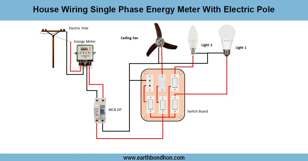
single phase traffic light wiring diagram
The one-phase traffic light control wiring diagram with a timer illustrates the connection of phase and neutral to the DP switch/MCB, timer relay, relays/contactors, and traffic lights to allow automated operation.
single phase traffic signal wiring connection:
Traffic lights wiring Single-phase wiring with a timer enables the automated switching of the red, yellow, and green lights. Phase and neutral AC supply wires of a single-phase supply are isolated through a DP switch or MCB and overcurrent. The timer relay is used to regulate the time of each signal, and the contactors or relays are used to alternate the traffic lights. Earthing is done well to avoid electric shock. Connection is illustrated in the wiring diagram below with supply -> DP switch/MCB-> timer relay-> relays/contactors -> traffic lights. Observing the sequence in the diagram provides the proper sequence of signals, safe working, and safety of the electrical elements. The system has found a lot of applications in small crossings, pedestrian crossings, or factory-related traffic management. Proper installation and testing will ensure that the traffic light system works well and lasts longer.
Work & Installation (Input → Output,)
- Input Supply: Single-phase 220–240V AC via DP switch/MCB.
- DP Switch / MCB: Provides isolation and overload protection.
- Timer Relay: Controls the duration of red, yellow, and green signals.
- Relays / Contactors: Switch individual traffic lights on/off according to timer sequence.
- Traffic Lights: Red, yellow, green lamps connected to relay outputs.
- Earthing: Traffic light frame and electrical panel grounded properly.
- Output: Traffic lights operate automatically with correct timing sequence, providing safe traffic management.
This installation is safe, efficient, and reliable in the operation of traffic lights.
Testing & Final Adjustments
Switch on the DP Switch/MCB and check the work of the timer relay after wiring. Confirm that all lights go on/off in the correct order as the program has been programmed. Check the voltage at every end of the traffic lights (~ 220 240 V). Check the contacts of the relay and the wires (wire concerning wire must be properly insulated to eliminate short circuits). Recheck the entire cycle a few times and ensure that there is proper sequencing of red, yellow, and green lights. Safety Continuity of earthing checks. As required, change the settings of timers to optimize traffic. Mark label wires and components for ease of maintenance. Proper testing would make sure that the traffic light system is reliable, and it does not pose an electrical risk, and also provides a smooth flow of traffic. Proper installation will ensure the timer, relays, and traffic lights can last longer and will offer safe and automated control of intersections or industrial areas.
Frequently Asked Questions - single-phase Traffic Light Control Wiring:
What is a single phase traffic light control?
A system that controls red, yellow, and green lights automatically using single-phase AC and a timer.
How is it connected?
Via DP switch/MCB → timer relay → relays/contactors → traffic lights.
Is earthing necessary?
Yes, for safety and to prevent electric shocks.
What voltage is used?
220–240V single-phase AC.
What does the timer do?
Controls duration of red, yellow, and green signals in sequence.
Can multiple lights be controlled?
Yes, each light is controlled via separate relay/contactors.
How to test the system?
Switch on supply, observe proper sequencing and timing of lights.
What protection is used?
DP switch or MCB protects against overload and short circuit.
Can it be used for industrial areas?
Yes, for small intersections, pedestrian crossings, and industrial traffic control.
Why follow the wiring diagram?
Ensures safe, efficient, and reliable traffic light operation.