
Wiring Diagram for Light Switch
Learn dipolar remote switch wiring for safe maneuvering of motors and appliances with remote ON/OFF control and electrical protection.

electrical maneuvering circuit
A dipolar remote switch allows the line and neutral to be safely maneuvered. It is widely applied to contactors or relays to remotely control high-current loads with safety and protection.
industrial remote switch wiring
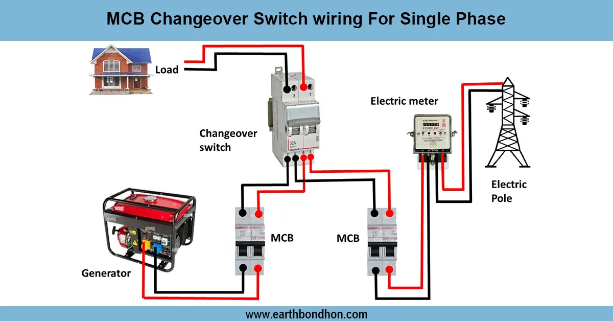
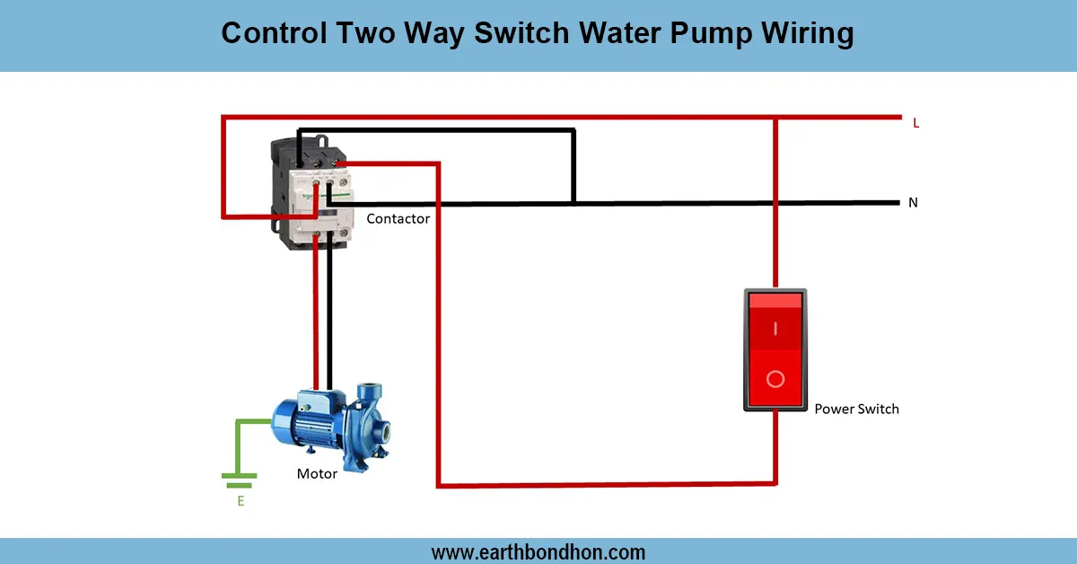
Dipolar remote switch wiring. Maneuver Remote Control Maneuver, Remote operation of motors or appliances using a two-pole switch in each line, live and neutral. A current-carrying MCB overload passes through the AC supply to the remote switch. The dipolar switch can safely switch ON/OFF the connected load some distance away. Increased current loads are commonly controlled by a contactor or a relay, whereby a remote switch controls low current to activate coils. Indicator lamps may be ON/ OFF. Proper wiring ensures safety during electrical conditions and eliminates back feeds and destruction of appliances. Testing is done to confirm that the remote switch works to open and close the load in the correct manner, the contactor works correctly, and the MCB trips correctly when fault conditions arise. It is widely used in industrial motors, water pumps, and lighting circuits to simply and safely manipulate remote operation.
Work & Installation (Input → Output Summary)
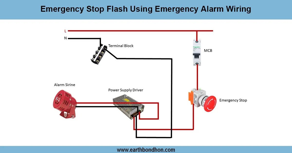
- AC Supply connects to main MCBfor protection.
- Supply goes to thedipolar remote switch (two-pole) controlling line and neutral.
- Remote switch output activates a contactor/relayif controlling high-current loads.
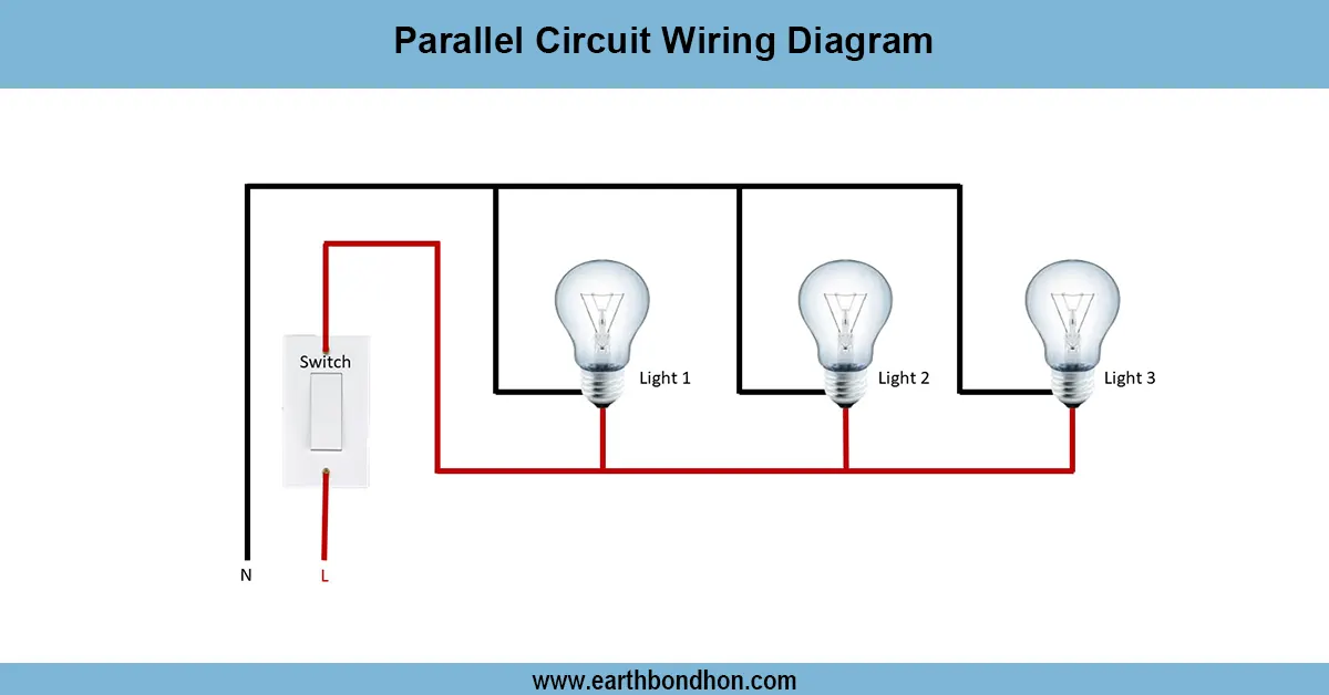
- Load (motor or appliance) connects through contactor output.
- Indicator lamps show load ON/OFF status.
- Proper wiring preventswhile allowing remote operation. short circuits, back-feed, and electrical hazards
Testing & Final Adjustments
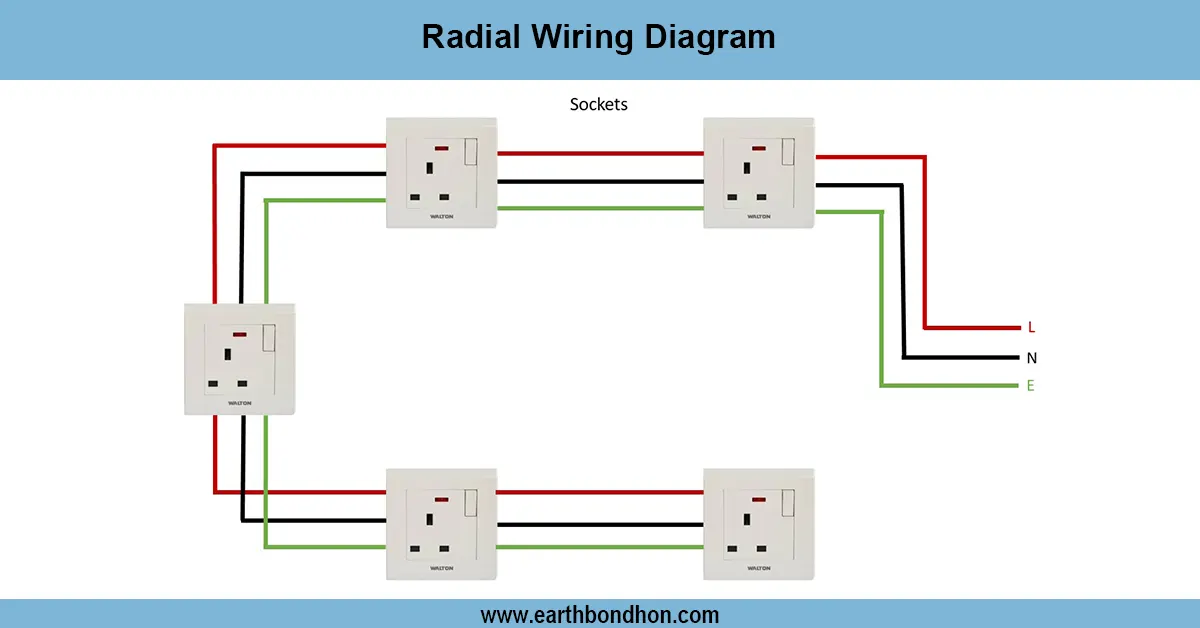
- Verify AC supply, MCB, dipolar switch, contactor/relay, and load connections.
- Switch ON/OFF remotely; confirm load operates correctly.
- Test contactor coil activation using remote switch; verify it handles high-current load safely.
- Inspect MCB operation under overload or fault conditions.
- Check indicator lamps for correct status display.
- Ensure proper insulation and secure mounting of all components.
- Test multiple ON/OFF cycles to confirm reliability.
- Verify line and neutral polarity at the dipolar switch and load.
- Confirm no back-feed into the supply line during remote operation.
- Document wiring, testing results, and load specifications for maintenance reference.
Frequently Asked Questions - Wiring Diagram for Light Switch:
What is a dipolar remote switch?
A two-pole switch that controls both line and neutral for safe remote operation.
Where is it used?
In motors, water pumps, lighting circuits, and industrial appliance control.
Why use a contactor with remote switch?
To handle high-current loads safely while the switch controls low-current coil.
Is MCB necessary?
Yes, for overload and short-circuit protection.
Can it operate multiple devices?
Yes, through properly rated contactors or relays.
How to test remote switch wiring?
Activate the switch and verify load operation and indicator lamps.
Is earthing required?
Yes, to prevent electric shocks from metallic parts.
Can I use it for single-phase and three-phase loads?
Yes, wiring may vary slightly based on load type.
What if load does not operate remotely?
Check connections, contactor coil, MCB, and switch polarity.
Does it prevent back-feed?
Yes, correct dipolar wiring ensures safe operation and prevents back-feed.