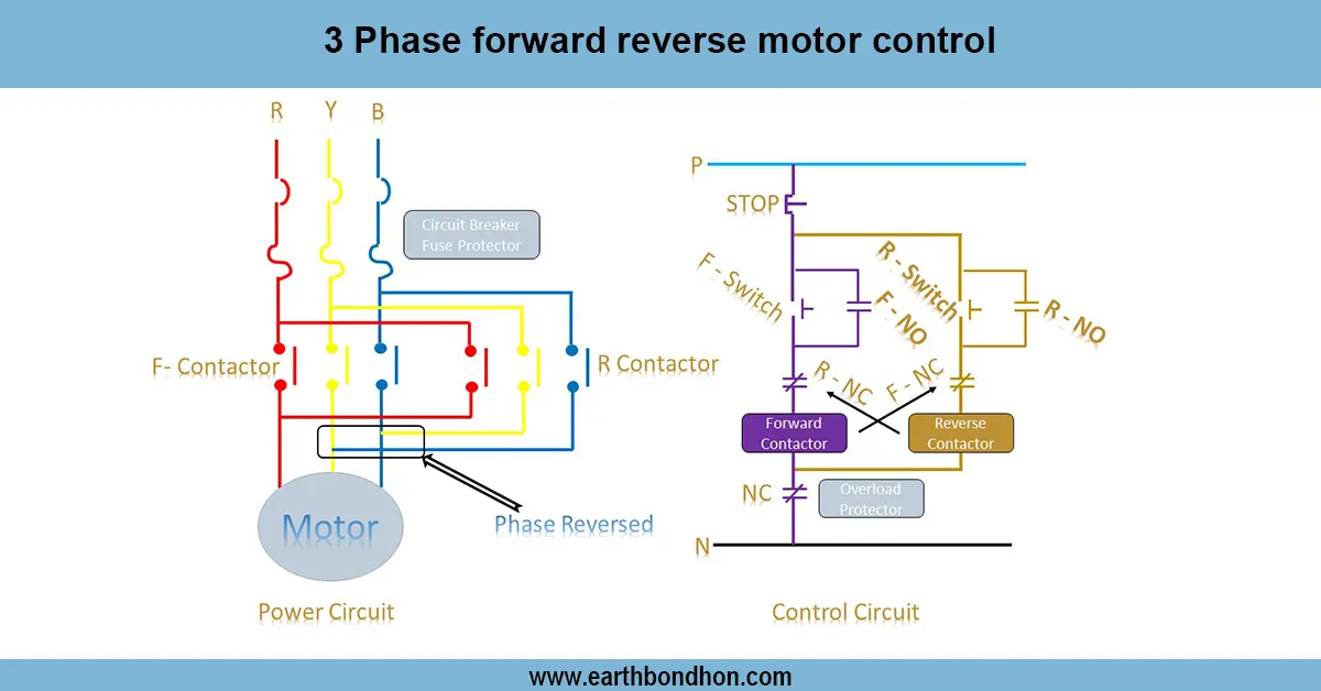
3-phase Motor Contactor Wiring Circuit Diagram
Learn how to control a 3-phase motor using a monopolar switch, including wiring diagram, start/stop operation, and safety precautions for industrial motors.

industrial motor start stop circuit
A 3-phase motor can be operated by a monopolar switch, which can be operated manually by connecting or disconnecting the supply to the motor. It can be safely and efficiently used in an industrial or small-scale setting using the protection equipment, such as MCBs and overload relays.
3-phase motor electrical safety
A monopolar switch is an easy way to manually start and stop motors with a 3-phase motor. The system will consist of a monopolar (single-pole) switch, optional contactor, overload relay and connection of the motor. The monopolar switch is a hand-operated switch to switch the motor circuit on. When the switch is switched ON, the motor is connected to the supply and it starts. By switching the switch, the motor supply can be turned off instantly. To be on the safe side and avoid overloading, a series of MCB or overload relay is advisable in front of the motor. This is a common connection with small 3-phase motors, pumps and equipment where manual ON/OFF is adequate. Wiring guarantees good operation, avoiding accidental short circuit, and manual control. Testing includes checking ON/ OFF functionality, supply isolation checking and proper functioning of motor protection devices.
Work & Installation (Input → Output Summary)
- Supply Voltage is routed through the monopolar switch.
- Switch ON energizes motor supply; motor starts.
- Switch OFF disconnects supply; motor stops immediately.
- Overload Relay or MCB provides protection against overcurrent.
- Optionalcontactor can be used for switching higher current motors safely.
- Wiring ensuressafe manual control and overload protection.
Testing & Final Adjustments
- Verify all connections between supply, monopolar switch, motor, and protection devices.
- Turn switch ON; motor should start and run smoothly.
- Turn switch OFF; motor should stop immediately.
- Test MCB or overload relay by simulating overload conditions to ensure proper tripping.
- Inspect terminals and switch contacts for secure and safe installation.
- Check earthing for motor and control circuit.
- Confirm smooth motor rotation without vibration or sparking.
- Test repeated ON/OFF operation for reliability.
- Verify motor direction if rotation matters for the application.
- Record all results for maintenance and operational safety reference.