table fan speed control wiring
Learn how to wire a table fan with a speed controller using a capacitor or an electronic regulator for smooth operation and multiple speed control safely.

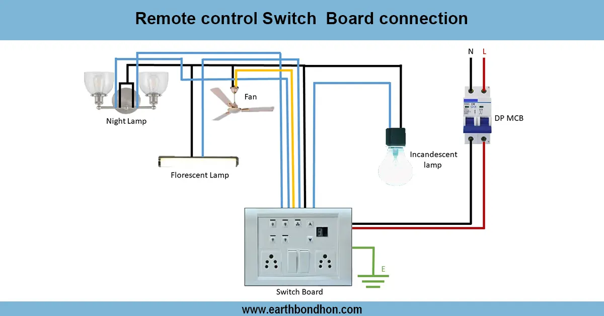
table fan speed regulator wiring diagram
The table fan speed controller wiring diagram demonstrates how to connect a live wire through a speed controller to the fan motor, allowing smooth multi-speed control with proper neutral and earth connections.
ceiling fan regulator wiring for table fan:
A table fan speed controller wiring allows users to control the speed of a single-phase AC fan safely. Traditional controllers use capacitor-based resistive control, while modern ones may use triac-based electronic regulators for smooth speed adjustment. The wiring generally connects AC live → speed controller → fan motor live, while the neutral wire goes directly to the motor. Some controllers include capacitor terminals for speed regulation in different steps. Proper earthing of the fan body and controller ensures safety. Using a speed controller improves comfort, reduces energy consumption, and increases fan lifespan. This wiring method is widely used in residential and office table fans for efficient multi-speed operation. Following the wiring diagram ensures correct speed control, safe operation, and prevents motor overheating.
Work & Installation (Input → Output,)
- AC Supply Input: Connect live (L) and neutral (N) wires from the mains.
- Connect the live wire to the input terminal of the fan speed controller.
- Connect the live wire to the input terminal of the fan speed controller.
- Output from Controller: Connect the output terminal to the fan motor live terminal.
- Neutral Connection: Connect the neutral directly from the mains to the fan motor neutral terminal.
- Capacitor (if used): Connect capacitor terminals according to the controller diagram for step-wise speed selection.
- Earthing: Connect the fan body and controller metallic parts to the proper earth.
- Operation: Adjusting the controller changes fan speed smoothly.
- Protection: Ensure a fuse or MCB is installed in the main line for safety.
- Output: Fan operates safely with variable speed control, reducing energy consumption and wear.
Testing & Final Adjustments
Connect a wire afterwards, then turn on the AC supply and verify the work of the controller. Turn the knob or press the speed buttons to ensure that the fan varies in speed without humming, flickering, or overheating. Checks on all wiring to ensure that it is secure and well insulated. Proper earthing of the fan body and controller should be made. Make sure that a controller has a high rating with the fan motor load to avoid breaking down. Check the various speed levels on several occasions to ensure that it is stable and that the control is step-by-step. Provide labels on the controller and wiring so that they can be easily maintained. Inspection will be done periodically to provide long-term reliability, safe operation, and energy-efficient fan control. Proper wiring and testing of the motor eliminates the overloading of the motor, short-circuiting, or electrical hazards, and improves the level of comfort of using the multi-speed operation.