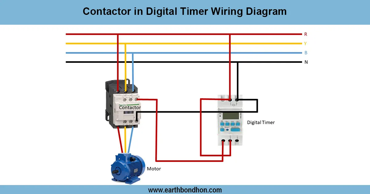
single phase Pump Motor Control Wiring
Learn how to install an auto timer for water pump motors with proper wiring. Step-by-step guide for automatic pump control, safety, and efficiency.

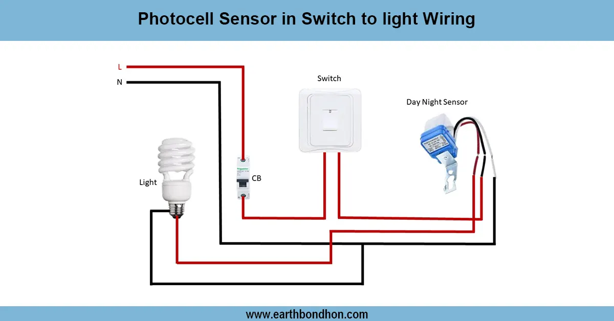
auto timer for water pump motor
In order to install an auto timer on the water pump motor, fit the timer switch in series with the contactor coil and supply line. The wiring is as MCB/Timer/Contactor/Motor. This would take care of the automatic ON/OFF control of the pump at a predetermined time without operating the pump manually.
water pump timer switch connection
Auto timer wiring water pump motors. This can assist in automating your water supply system to save electricity and prevent damage to the motor. Using a timer, the pump can be programmed to run on or off at designated times, so the water flow remains constant and manual labor is minimized. This system has gained considerable popularity in residential buildings, apartments, and businesses to prevent over-pumping as well as dry-running.
The system comprises a digital/analog timer switch, MCB, and contactor to enhance adequate protection. The device provides automatic control of the electricity supply by connecting the pump motor with the timer based on the programmed schedule. By using this type of wiring, convenience is brought out, as well as the life of the pump motor is prolonged.
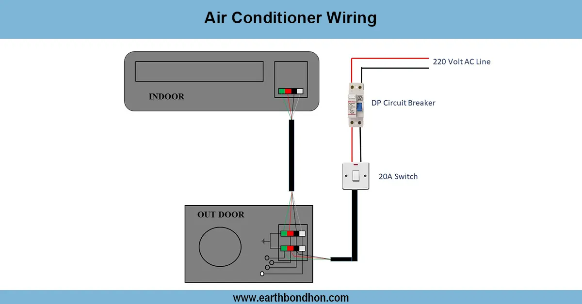
Work / Installation (Inputs → Outputs)
The installation begins with the main supply line attached to an MCB to ensure safety. The phase wire is connected to the auto timer switch, out of the MCB. The coil of the contactor is connected to the timer output and the pump motor. As the timer goes off, the contactor becomes active and current is fed to the motor. Supply wires directly to the motor and timer are the neutral ones.
This wiring requires that the pump be started only according to the scheduled program. A digital timer is more precise and has many cycles ON/OFF in a day, whereas a mechanical timer is basic and inexpensive. It should be properly earthing and MCB/RCCB protected.
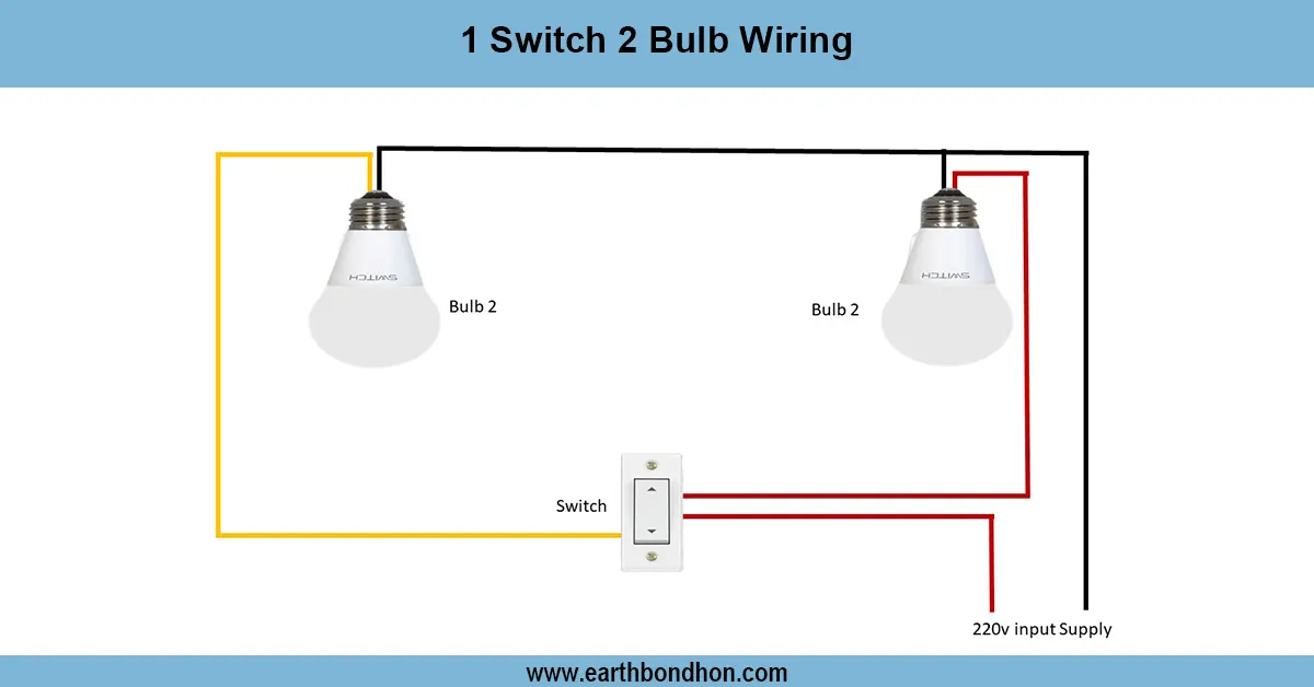
Testing & Final Adjustments
Once wired, verify the circuit by running a short (e.g., 1 minute ON, 1 minute OFF) cycle. Make certain that the display on the timer is functioning and that the contactor clicks ON/OFF as desired. The regulator pump motor will automatically start and stop at the set time.
A non-running motor: Check the input/output connections on the timer and ensure that the MCB is ON. Ensure the timer is not under manual override but on Auto Mode. Turning ON/OFF schedules based on water demand, i.e., morning and evening operation.
Lastly, examine wiring, loose connections, sound insulation, and grounding. This eliminates overheating, sparking, and accidental shocks. The auto timer is built to ensure energy-saving, safe running of the motor, and continuous water supply with appropriate adjustments.