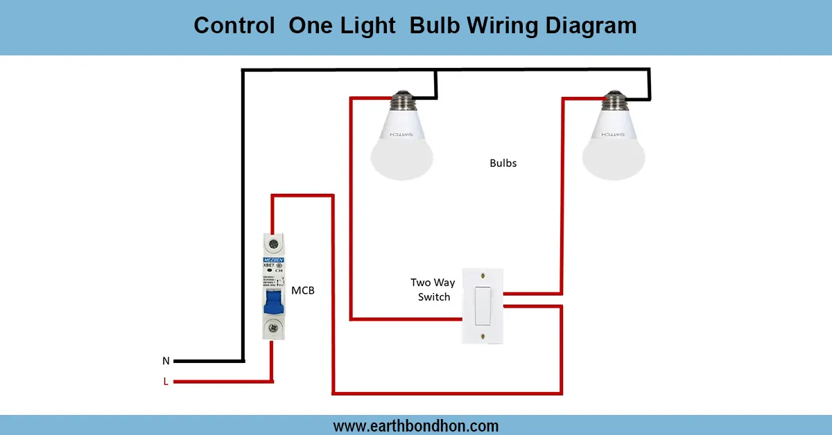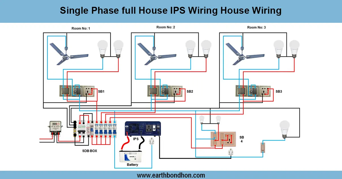

Single Phase House wiring circuit diagram
Simple 3-bulb house wiring diagram showing connections of bulbs with switches and power supply for safe and efficient home lighting control.

3 bulb switch wiring
A 3-bulb home wiring diagram illustrates the wiring of three independent bulbs and switches to one power supply, enabling the user to control them independently since separate power sources are used to independently turn them on/off with ease of harnessing the power lighting in the house.
3 Bulb House Wiring Summary & Components:
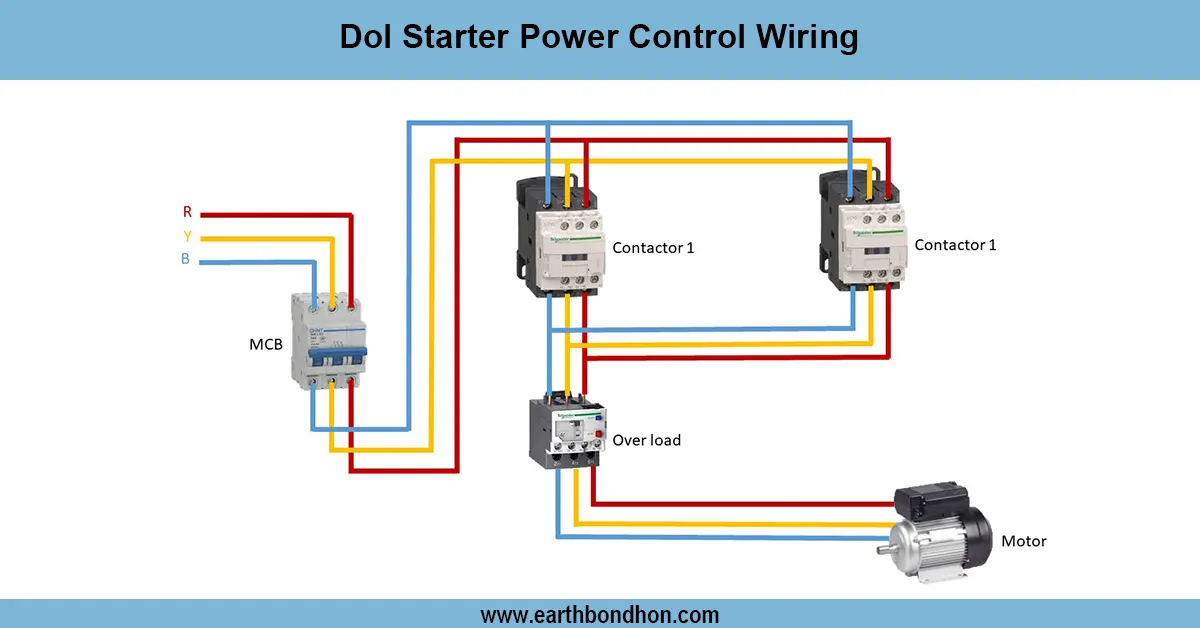
Power Supply: Single phase AC supply (Live, Neutral, Earth)
Switches: One switch per bulb for individual control
Bulbs: Connected between switched live and neutral
Safety: Proper grounding and insulation mandatory
home lighting circuit diagram
The three-bulb house wiring system enables one to control three bulbs using individual switches and a common power source. This wiring is a widely accepted system in houses having lighting systems with more than one light in the room. The bulbs have separate controls and switches in the sense that they are each attached to different switches. Wiring is done using live conductor (phase), neutral, and earth, which are connected with respect to electricity standards to provide safety. Electrical hazards can be avoided by having proper insulation and grounding. This guide explains the method of wiring bulbs, switches, and the power lines effectively, whilst ensuring the safety of the electricity in the residential lights.
residential lighting wiring
| Component | Connection | Description |
|---|---|---|
| Live Wire (L) | Connected to all switches | Supplies power to switches controlling bulbs |
| Switches | One per bulb | Controls power flow to each bulb |
| Bulbs | Connected to switched live and neutral | Emit light whenthe switch is ON |
| Neutral Wire (N) | Common connection to all bulbs | Completes the electrical circuit |
| Earth Wire (E) | Connected to bulb fixtures and metal parts | Ensures safety from electric shock |