Capacitor Connection in Ceiling Fan
Learn ceiling fan in speed controller wiring with diagram, step-by-step connection, input to output setup, and testing for safe and smooth fan speed control.

ceiling fan in speed controller wiring
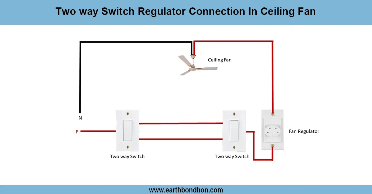
Wiring Ceiling fan speed controller wiring consists of the phase via the regulator to the fan, and the neutral wire is hardwired and hence, adjustment of speed can easily be made.
ceiling fan switch and regulator wiring
This ceiling fan's speed controller wiring diagram demonstrates the connection of a regulator and a fan to facilitate smooth control of speed. The switchboard phase (live) wire traverses the speed controller (fan regulator) and then on to the fan, with the neutral conductor then being connected to the fan. This wiring provides the controller with the chance to regulate resistance or voltage in order to control the fan speed. The correct wiring diagram would point out the input phase to the regulator output to the fan, and the neutral to the fan connections. The correct installation will aid in preventing overheating and will also be energy-saving and extend the life of the fan. Modern electronic fan regulators have superior speed control over the traditional resistive regulators.
Work / Installation (Inputs → Outputs)
Under this type of wiring, the switching board input phase is connected to the speed controller. The controller has the output wire that goes to the fan phase terminal. The supply neutral makes a direct connection to the neutral connection of the fan. In this manner, upon rotation of the regulator knob, it alters the voltage or resistance to the fan, thereby regulating its speed. The old regulators are drop voltage-based based and the new electronic regulators are capacitor-based or triac-based based depending on which offer a continuous range of speed. Always offload the main supply during installation, use appropriate insulated wiring, and make tight terminal connections to prevent overheating and sparking.
Testing & Final Adjustments
Wire and turn on the main supply, then use the wall switch. Turn the speed controller knob to ensure that the fan is operating at varying speeds. Begin at minimum and work to maximum. Check the regulator output connections unless you start the fan at low speed. Make sure the controller does not make unusual noise, vibration, or overheat. Test the wall switch ON/OFF status to ensure total isolation of the circuit. Mark the switchboard so that it can be identified. When an electronic regulator is being used, ensure stepless regulation without pulsation. Lastly, check out the insulation, earthing, and tightness of the wires to prevent further risks.