power-factor-capacitor-bank-connection
Learn 3-phase line PFI panel wiring, star-delta starter connection, and PF improvement with step-by-step installation, work process, and testing guide.
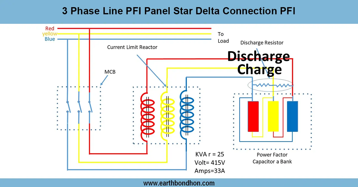
star delta starter connection:
In the industries, a 3-phase line PFI panel that is connected in star-delta is used to control the loads of the motor and enhance the power factor. Reactive power is regulated by the PFI panel using capacitor banks, and the star-delta starter provides a safe start of the motor. All these work together to make things more efficient, safer in terms of power bills, and equipment protection.
3 phase line protection relay:
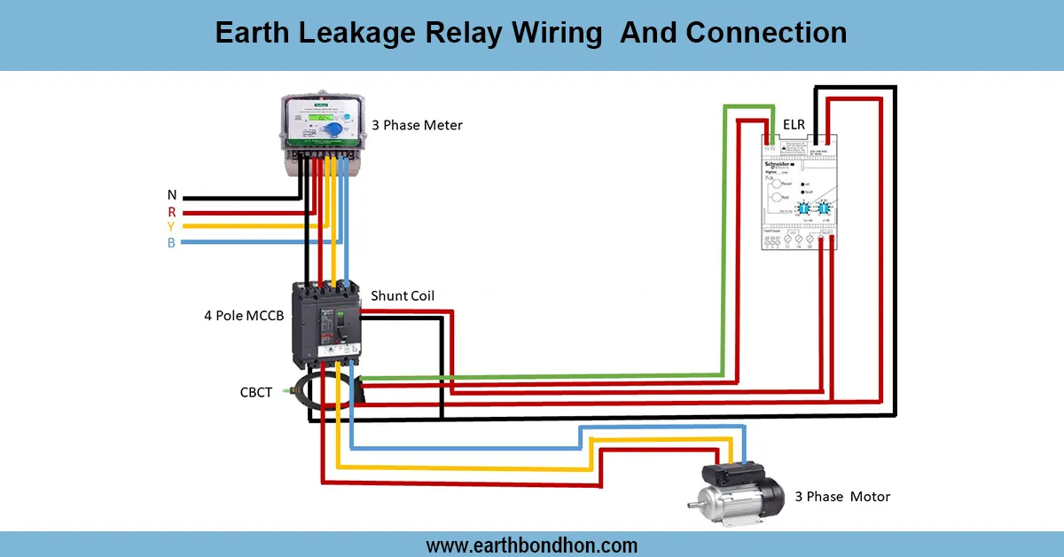
A 3-phase line PFI panel connected in star-delta will guarantee that the motor will work efficiently and the power factor will be better in industrial systems. PF is improved using capacitor banks and APFC relays on the PFI panel, and the star-delta starter decreases starting current in 3-phase induction motors. Such a combination reduces the losses of energy, eliminates the penalties of utilities, and ensures stable operation. Protection relays are used to protect the system against overcurrent, earth faults, and voltage changes. To facilitate the load management, it is necessary to ensure that the HT supply is properly wired to the LT panel and the star-delta starter and PFI panel are connected. With the PF being corrected to a value near unity, the efficiency and reliability of the entire system are enhanced.
⚡ Work & Installation (Input → Output):
- HT Line enters the transformer (11kV/33kV → 400V LT).
- LT Panel distributes 3 phase supply to busbars.
- Star-Delta Starter connects to induction motors for safe starting.
- PFI Panel (Capacitor banks + APFC relay) connects parallel to busbar.
- System maintains PF close to unity and protects motors via relays.
Testing & Final Adjustments:
The system should be subjected to intensive testing after wiring. Check insulation resistance, permanency, and relay operation. Output of the check transformer LT to a balanced 3-phase voltage. Test the star-delta starter. Run motors, test to ensure a smooth transition between star and delta with no trips. Check the switching of the APFC relay and the capacitor bank to check the PFI panel operation. Regulate capacitor stages to sustain PF at 0.95 -1.0 at different loads. Test that the fault simulation with overload and earth fault relays operates correctly. Measure starting current, running current,t, and PF of the recmotor before switching to the capacitors. Load test in various conditions to ensure a stable operation. Lastly, seal all terminations, verify correct earthing, and issue a log sheet of test results.