Float Switch Connection Diagram
Learn float switch with contactor wiring to automatically start/stop water pumps based on tank level, ensuring motor protection and efficient operation.

submersible pump control circuit
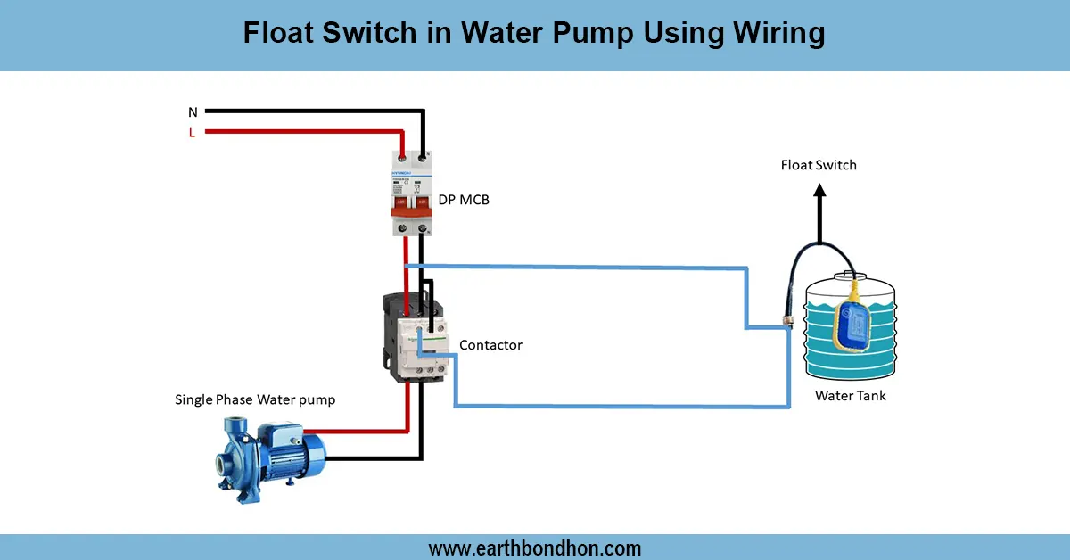
The water pumps are automatically activated by a float switch using contactor wiring depending on the level of the tank. Correct connection guarantees safe running of the motor, avoids dry running and gives a regular supply of water.
contactor pump control diagram
A contactor-wired float switch enables pumps to be controlled automatically depending on the water levels. The float switch is extended in series with the coil of the contactor. As the water level decreases, the contactor coil is energized by closing the float switch and causing the pump to run. When the water hits the upper level, the float switch opens, de-energizes the contactor, and shuts off the pump. The system will prevent dry running of the pump motor and provide confidence in the tank water management. The wiring consists of an AC supply, a float switch, a contactor coil, a pump motor, and optional indicator lamps. Safe high-current pump switching can be performed by using a contactor so that the float switch does not have to operate directly under full load. The process of testing will entail high and low water level simulation, and the pump should be tested to ensure it starts and stops pproperlyflfloatwitch, fitted with contactor wiring, is common in residential, commercial, and industrial water pumping.
Work & Installation (Input → Output Summary)
- AC Supply connected to float switch circuit.
- Float Switch contactor coil. closes on low water, energizing
- Contactor Contacts close, supplying power to pump motor.
- Pump starts filling the tank; float switch opens on high water, de-energizing contactor.
- Pump stops automatically, preventing dry running.
- Optionalindicator lamps show pump operation status.
- Proper wiring ensures automatic control, motor protection, and energy efficiency.
Testing & Final Adjustments
- Inspect all wiring: AC supply, float switch, contactor coil, pump, and indicators.
- Simulate low water; the float switch should close and energize the contactor, starting the pump.
- Simulate full tank; float switch should open, de-energize the contactor, and stop the pump.
- Test indicator lamps for correct ON/OFF operation.
- Ensure the float switch moves freely and the contactor operates reliably.
- Repeat multiple cycles to confirm proper automatic operation.
- Check terminals for secure and insulated connections.
- Ensure the pump does not run dry at any point.
- Verify wiring follows electrical safety standards.
- Record observations and maintenance notes for safety documentation.