
Hostel Wiring Diagram
Learn hostel wiring diagram with single line layout, load distribution, lighting, fans, sockets, and safety devices for proper electrical installation.

electrical wiring for hostel rooms
Hostel wiring diagrams demonstrate how electricity is distributed to hostel rooms, fans, lights, and sockets via the hostel wiring board, which has protective devices.
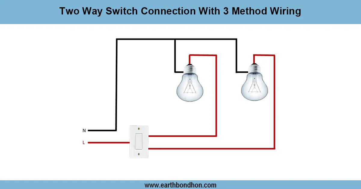
hostel room switch board connection
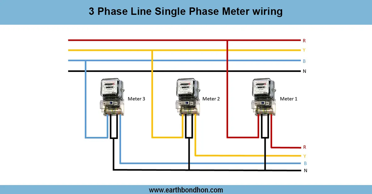
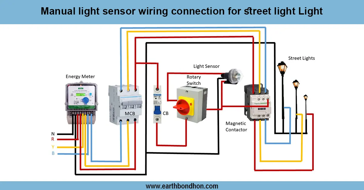
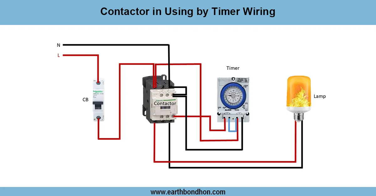
Hostel wiring diagram- This is used to show the distribution of power in a hostel where the main supply is fed to various rooms, corridors, and other common places. It displays the direction of phase, neutral, and earth wires, including protective equipment such as MCBs, RCDs, and earthing systems. The main supply usually comes in via an energy meter and distribution board, where circuits run out to lighting points, ceiling fans, sockets, water heaters, etc. The switchboards in each room control lights and fans, and the common rooms have separate circuits. It is important to ensure proper sizing of the wire, earthing, and distribution of loads to prevent overloading and provide electrical safety. Emergency lighting, fire safety connections, and backup generator / UPS integration in hostels are also brought out in the wiring diagram. The use of standard wiring codes guarantees a safe power supply to the occupants of the hostel.
Work / Installation (Inputs → Outputs)
This supply of inputs is fed into the hostel by an energy meter and a main switch. Here, power is supplied to the main distribution board with MCBs / RCCBs. There are separate circuits for rooms, corridors, the kitchen, and the common halls. Phase and neutral are fed to each room through sub-boards that control fans, lights, and sockets. All wiring has earthing to avoid shocks. Separate circuits are given to heavy loads like geysers or air coolers. Safe wiring is done in the cupboards, with conduits and switches fitted on the height switch boards. Fire alarm systems and emergency exit lights are tied to emergency power supplies such as UPS or generators. This guarantees power in hostels.
Testing & Final Adjustments
Once installed, continuity and insulation resistance are to be tested in each circuit. Ensure that the correct connection is made between phase, neutral, and earth, a nd that earthing resistance is within safe limits. Switch on the supply, check lighting circuits, fans, and sockets in each room. Operation MCB/RCCB to test that they trip when faults occur. Transfer should also be checked on backup power circuits. Labeling of all the DB circuits, room circuits, a nd emergency circuits is useful in maintenance. Any loose connections need to be fixed, and wires contained within switchboards arranged tidily. Testing should be followed by safety checks before the system is handed over to be use. The right testing and certain final adjustments will provide a safe and dependable power supply inside the hostel.