Submersible Pump Control Box Connection Wiring Diagram
Learn how to wire a submersible pump control box including MCB, overload, starter, and float switch for automatic operation and motor protection.

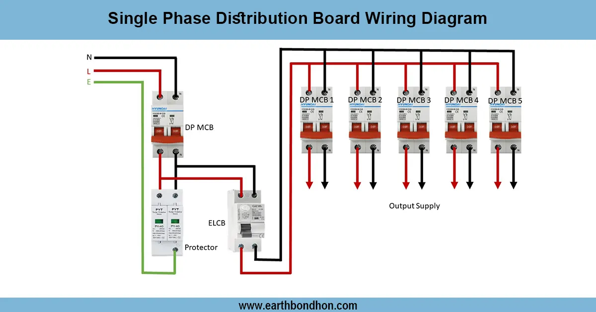
submersible pump control box wiring diagram
The wiring of a submersible pump control box provides the automatic operation, overload and safe connection of the pump motor with MCB, starter, and float switch.
submersible motor control box connection:
A Submersible Pump Control Box Wiring Diagram illustrates the way to join the system with a pump motor and a control box that should control the start/stop of the motor and secure the motor. The control box is generally designed to contain MCB (Miniature Circuit Breaker), overload relay, starter contactor, capacitor (when it is single-phase) and a float switch used to detect the water level. The control box is fed by the power supply and the wiring is to be properly done to ensure safe operation. When water is up the float switch is activated and when water is down the pump is switched off. The overload protection will not allow damage of the motor when there is a lot of current. The wiring is also done in terms of standard phase, neutral, and earth color codes which are also safe. This serves in domestic, agricultural and industrial water pumping systems to enhance efficiency, avoid dry running and increase the life of the motor.
Work & Installation (Input → Output,)
- Power Supply: Connect incoming single-phase or three-phase supply to the control box.
- MCB: Install MCB for short-circuit and overload protection.
- Contactor/Starter: Connect main contactor to the pump motor for ON/OFF control.
- Overload Relay: Connect in series with motor for thermal protection.
- Float Switch:Float Switch: Wire float switch in control circuit to start pump automatically based on water level.
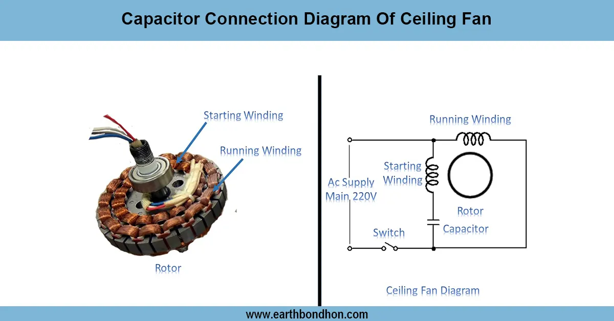
- Capacitor (if single-phase): Connect start/run capacitor to motor terminals.
- Earth Connection: Ensure proper earthing of control box, motor, and metallic parts.
- Control Wiring: Connect push buttons (if manual operation) and indicator lamps.li>
- Testing: Verify pump starts and stops automatically and overload trips correctly.
- Final Adjustment: Label all circuits and ensure neat wiring for easy maintenance.
Testing & Final Adjustments
WIRE After wiring connect ON the main supply. Test automatic operation Simulates high and low water levels with the float switch. Note the start up and shutdown time of the pump. Check overload relay, simulate high current and make sure it snaps. Operation of short circuit protection Test MCB. Check indicator lamps and control push buttons to make sure they work well. Check connections, wires and terminals of tightness and insulation. Make sure proper sequence of phases of 3-phase motors. Earthing is the proper earthing to avoid electrical shocks. Following numerous test cycles, verify that everything is running well, the automatic water level control and overload or short circuit protection. Proper testing enhances the life of pumps, eliminates dry running, and safety and efficiency of operations.