
Automatic Timer Relay Using Alarm
Learn automatic timer relay wiring using an alarm for delayed activation/deactivation in industrial or home circuits with safety and precise control.

relay alarm automation wiring
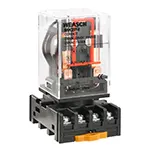
Delayed activation of circuits using automatic timer relay that has audible alarm. It operates reliably, safely and in precise applications in industry and home through timer relay, protection devices and control wiring.
electrical timer alarm wiring
A delaying circuit with an audible alarm can be operated with an alarm-operated automatic timer relay. It is made up of a timer relay, alarm, power supply, protective devices, and control wiring. The timer relay will wait a preset delay, then energize the alarm or connected load when the timer relay is activated. This is commonplace in industrial equipment, safety alarms, and home automation, to allow electrical equipment to be notified of a time-delayed alert, a warning, or to be controllable. Correct operation, avoiding simultaneous overloads, and protecting devices with MCB/fuse and thermal protection are all made possible by proper wiring. Installation: To connect, supply, and output terminals to alarm/load, and provide proper polarity, earthing, and insulation. Testing is done to check the functionality of timer delay, alarm activation, and protective devices to make sure they are safe and reliable.
Work & Installation (Input → Output Summary)
- Power Supply enters the timer relay circuit.
- Timer Relay is set for desired delay duration.
- Output Terminals connect to the alarm or load.
- Protective Devices (MCB/Fuse) safeguard the circuit.
- Timer Activation starts the countdown.
- After Delay, the relay energizes the alarm or connected load.
- System automatically switches off when the timer elapses or manually if needed.
Testing & Final Adjustments
- Verify insulation of supply lines and alarm connections.
- Set timer for a test delay and energize the circuit.
- Observe alarm activation after preset delay.
- Test MCB/fuse and any overload protection for proper operation.
- Ensure wiring polarity and earthing are correct.
- Simulate power on/off scenarios to check timer reliability.
- Verify relay contacts switch smoothly without sparking.
- Adjust timer settings for precise delay as needed.
- Inspect connections for secure fastening and safety.
- Record operational results for maintenance and future reference.